AFFZP0BB – ACE3 – User Manual Page – 35/139
6.2.7 Connection of Hall sensors
When the PMSM is of the BLDC type, must be controlled with a six steps inverter
(trapezoidal wave shape). A PMSM is a BLDC when, by turning its shaft lightened,
the electromotive force between two motor terminals is of the shape trapezoidal.
To control BLDC motor with Zapi inverter, it is necessary to three Hall sensors. Hall
sensors power supply can be +5 or +12 V.
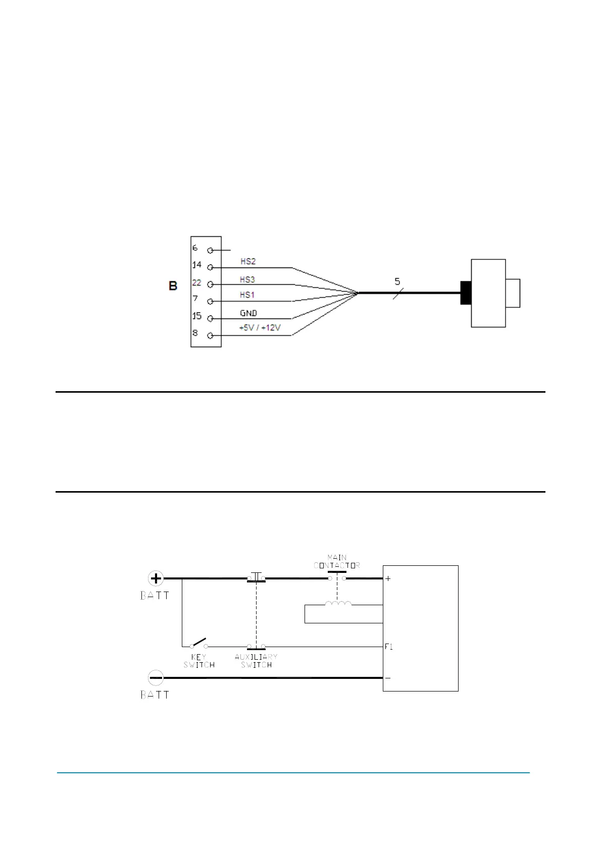
B8 +5V/+12V positive supply.
B15 GND negative supply.
B7 HS1 Hall sensor 1.
B14 HS2 Hall sensor 2.
B22 HS3 Hall sensor 3.
Connection of Hall sensors.
U VERY IMPORTANT
It is absolutely mandatory to specify in the commercial order the type of
sensor to be used, in terms of supply voltage, electronic output and number
of pulses per revolution, configuration of hall sensors and the sensor
sequence when the rotor is spinning because the logic unit and the software
must be set in the correct way by Zapi lines.
6.2.8 Main-contactor and key connection
- The connection of the main contactor can be carried out as the following figure.
- The connection of the battery line switches must be carried out following
instructions from Zapi.