AFFZP0BB – ACE3 – User Manual Page – 33/139
connection (pointed by the arrow in the image) must be sized taking into account
both thermal and voltage drop problems and considering the current drawn from the
battery by the overall system.
4 The complexity of today systems needs more and more data, signal and information
must flow from a node to another. CAN is the solution to different problems that
arise from this complexity
- simple design (readily available, multi sourced components and tools)
- low costs (less and smaller cables)
- high reliability (fewer connections)
- ease of analysis (easy connection with a pc to sniff the data being transferred onto
the bus).
6.2.4 Wirings: I/O connections
- After crimping the cables, verify that all strands are entrapped in the wire barrel.
- Verify that all the crimped contacts are completely inserted in the connector
cavities.
U A cable connected to the wrong pin can lead to short circuits and failure; so,
before turning on the truck for the first time, verify with a ohmmeter the
continuity between the starting point and the end of signal wires.
- For information about the pin assignment see chapter 4.
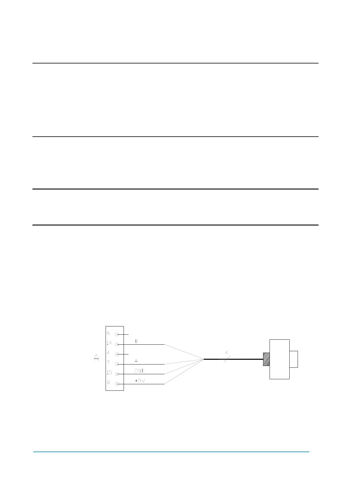
6.2.5 Connection of the encoder
ACE3 controller can handle different types of encoder. To control AC motor, it is
necessary to install an incremental encoder with two phases shifted by 90°. The
encoder supply can be 5 V or 12 V.
A8 +5V/+12V positive supply.
A15 GND negative supply.
A7 ENC A phase A.
A14 ENC B phase B.
Connection of encoder with +5 V supply.