AFFZP0BB – ACE3 – User Manual Page – 79/139
8.8 Throttle response
The ACE3 controls the truck speed by means of a not linear function of the
accelerator position, as to provide a better resolution of the speed control when the
truck is moving slowly.
For the definition of such response, the following parameters are used:
THROTTLE 0 ZONE [% of MAX VACC]
THROTTLE X1 POINT [% of MAX VACC]
THROTTLE Y1 POINT [% of MAX SPEED]
THROTTLE X2 POINT [% of MAX VACC]
THROTTLE Y2 POINT [% of MAX SPEED]
THROTTLE X3 POINT [% of MAX VACC]
THROTTLE Y3 POINT [% of MAX SPEED]
The speed remains at the FREQUENCY CREEP value as long as the voltage from
the accelerator potentiometer is below THROTTLE 0 ZONE. Basically this defines a
dead zone close to the neutral position.
For higher potentiometer voltages, the speed setpoint grows up as a polygonal
chain defined by the following table of points.
Throttle signal
[% of MAX VACC]
Speed setpoint
[% of MAX VACC]
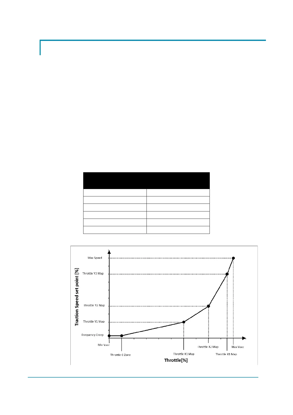
0 FREQUENCY CREEP
THROTTLE 0 ZONE FREQUENCY CREEP
THROTTLE X1 POINT THROTTLE Y1 POINT
THROTTLE X2 POINT THROTTLE Y2 POINT
THROTTLE X3 POINT THROTTLE Y3 POINT
MAX VACC MAX SPEED
The following graph better displays the throttle – speed relationship.