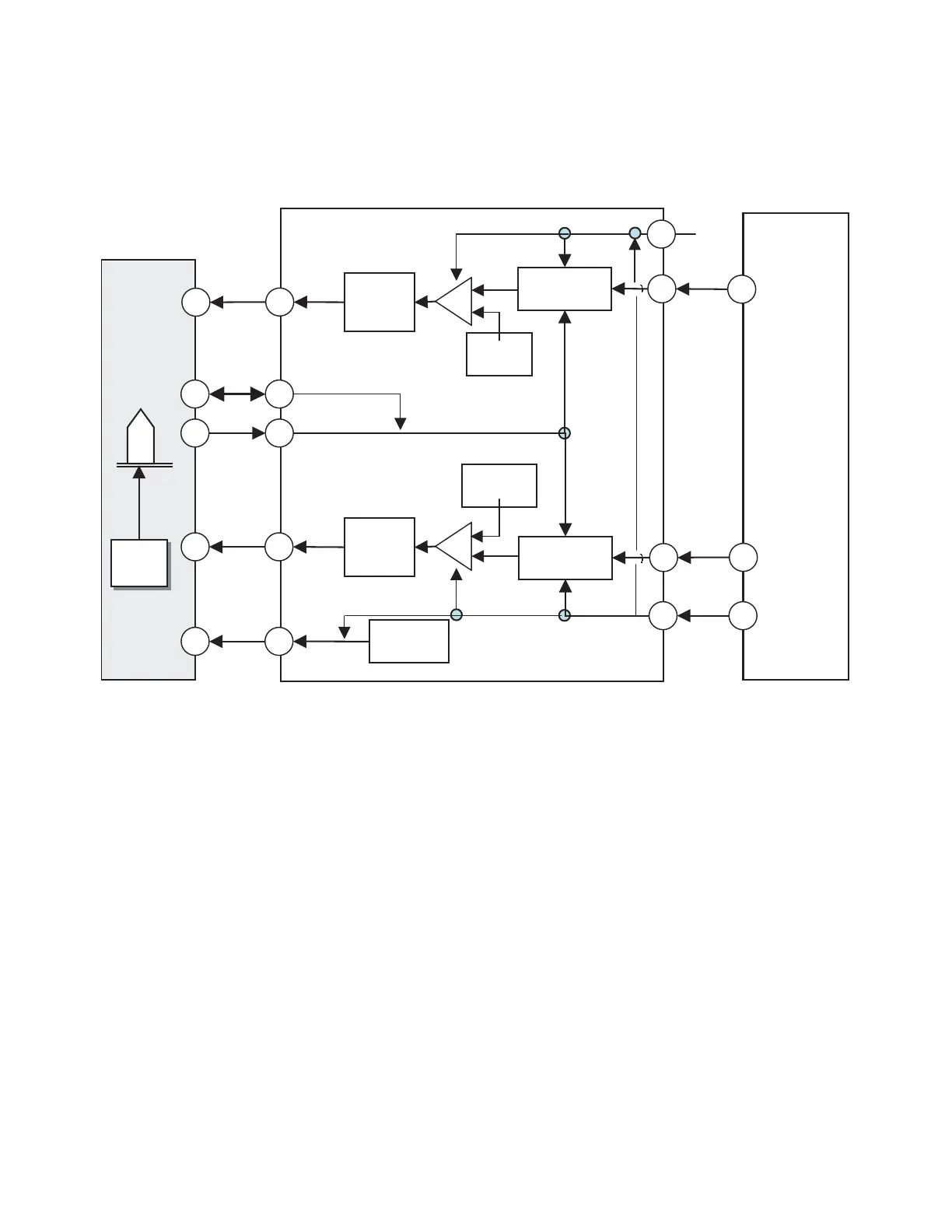
5. ALPC(Automatic Laser Power Control) Circuit
1) Block Diagram
2) ALPC(Automatic Laser Power Control) Circuit Operation
ALPC function in CD-R/RW,DVD+R/RW analog front-end is for constant power level control purpose.
Based on the accurate power sensor(FPD) in OPU, ALPC feedback loop maintains constant power level against
laser diode’s temperature variation.
There are two power control loops in uPC3330, which are used with different combination for different applications.
Generally, the first ALPC loop is used for read-power control. The 2nd ALPC loop is used for write(erase) power
control for CD-R/RW and DVD+R/RW disc.
Owing to the small signal level in read-power control mode, the first ALPC loop amplifies the FPD signal to enhance
the accuracy of read power control. The built-in 10-bit DAC(VRDC_DAC) is used to set the read power level.
Moreover, the 2nd ALPC loop is used for high power control. The built-in 10-bit DAC(VWDC1_DAC) is used to set
the wanted power level.
And the register VWDC1G is employed to adjust the gain of FPD signal.
The following potentiometers(VRDC_DAC, VWDC1_DAC, and VWDC2_DAC) and amplifiers (VRDCG and
VWDC1G) are used to set the wanted levels of the output pins RLD, WLD, and PELD