ZONEMASTER MAXIPOINT V2 DAMPER CONTROL SYSTEM - Installation Manual
4
4) Conguration
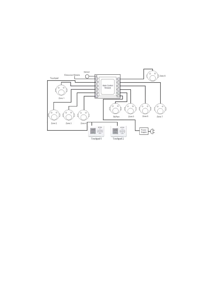
MaxiPoint V2 is a star architecture system for communications between
the main control module, extension module, 8 or 16 zone dampers and
upto4touchpads.Figure1and2showtwodifferentcongurations
covering 8 & 16 zones. Figure 3 shows the linking of the main module to
the extension module and the touchpads.
Eight motorised dampers can be connected to the main control module.
In addition, there is a dedicated bypass port where a damper is used to
return the supply air directly to the return air duct. (See Spill/Bypass Mode
on Page 12 )
Extension Module
An extension module can be plugged into the main control module to
expand the number of zones to 16, as shown in Figure 2. A separate 24
VAC power supply is required for the power supply to the 8 extra zones.
The cabling of the MaxiPoint V2 is straightforward. A cable with central
latched plugs connects a motorised damper to the relevant output port
clearly marked on the main control or extension module.
Figure 1: MaxiPoint V2 Main Control Module with
2 Touchpads and 8 dampers