ZONEMASTER MAXIPOINT V2 DAMPER CONTROL SYSTEM - Installation Manual
7
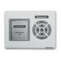
6) Component Installation
6.1 Mount the main control module and/or
extension module (if using more than
8 zones) by screwing the box(es) to a
roof frame or Polyaire Diffusion Fitting
(PDF).
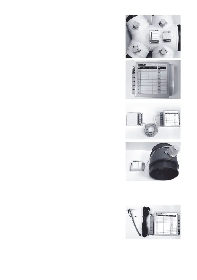
6.2 Remove thetwo-sidecoversonthe
main control module so that all the
LEDs and sockets for zone dampers
are exposed.
6.3 If extension module is used connect
main module to extension module at
the‘E’portsonbothmoduleswitha1
metre left latched cable (provided).
6.4 Usepre-testedcabletoconnect‘Z1’
port on the main control module to the
motorised damper of the 1st zone.
6.5 Repeat step 6.4 to connect other zone
dampers, including bypass damper
(‘B’port)ifinstalled,totheirrelevant
zone ports on the main control module
and extension module.
6.6 Mount the supply air sensor in the
supply air duct between the fan coil
andtherstdamperandpushthe
plug of supply air temperature sensor
into the socket on the main control
module (Optional).