RFSoC Data Converter Evaluation Tool User Guide 22
UG1287 (v2018.2) October 1, 2018 www.xilinx.com
Chapter 3: Hardware Design
ADC Control Switch
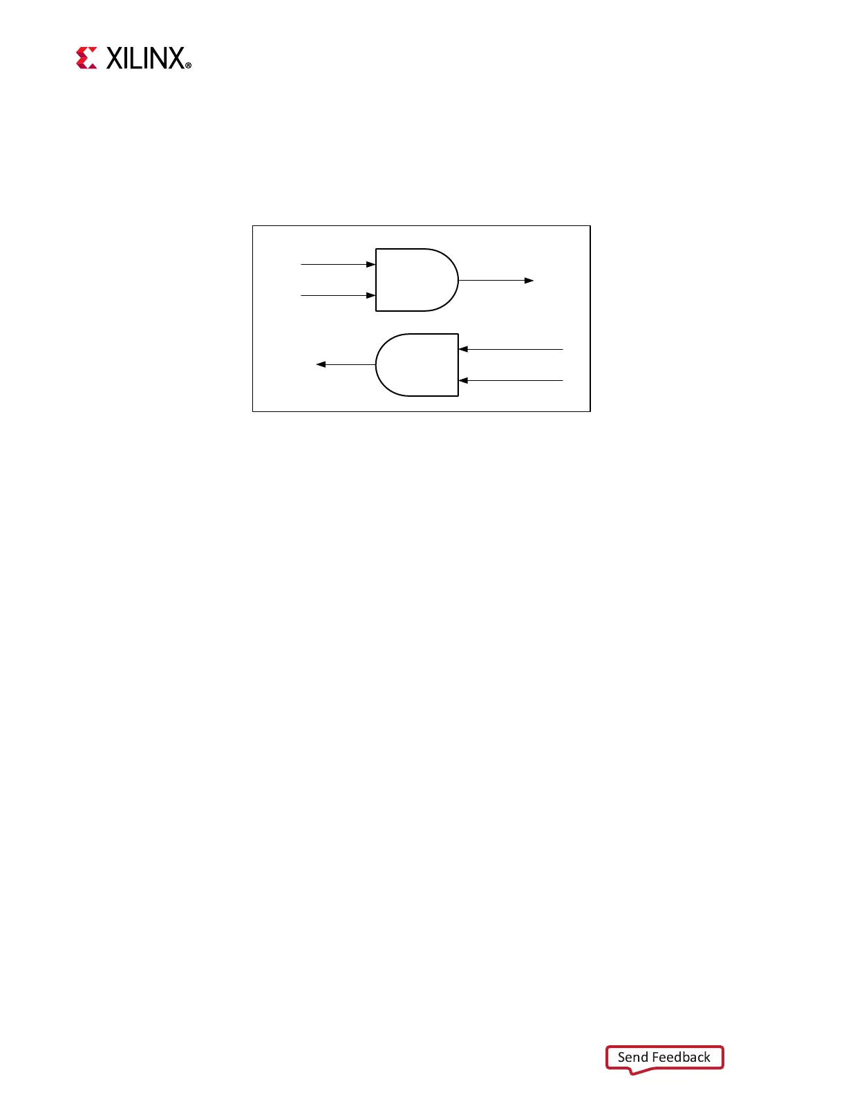
The control switch is the final control logic before the streaming interface is connected to
the ADC. This logic controls the streaming path and also helps to synchronize all the stream
interfaces when required through software control. Figure 3-9 shows the control switch.
The channel select signal acts as a channel start/stop signal. This signal exists individually
for all channels and can be used to control each channel independently. This is done using
PS-GPIOs through the EMIO interface that are in turn controlled by software.
The control switch controls TVALID input to FIFO and TREADY input to ADC.
I & Q Merge Logic
The IQ datapath for RF-ADC is shown in Figure 3-10. This pipe can capture IQ data while
maintaining synchronization and coherency. The data is captured in an interleaved fashion
i.e., eight samples of I data and eight samples of Q data. The AXIS combiner IP is used to
combine I and Q streams.
Alternatively, you can select a Real channel only (in which case, the width converter IP is
used to convert the incoming 128-bit Real data to 256-bit Real data). Finally, the data is
stored into an AXIS FIFO.
X-Ref Target - Figure 3-9
Figure 3-9: Control Switch
Channel Start
Tvalid Out to FIFO
Tready
Control
Switch
Control Switch
Tvalid
Channel Start
Tready Out to ADC
X21241-090918

 Loading...