Configuration manual for 2N IP intercoms
•
•
•
•
•
•
•
•
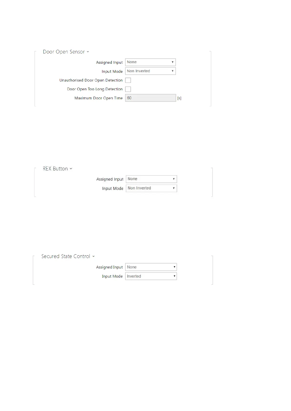
Assigned Input– define one (or none) of the logic inputs for open door detection.
Unauthorized Door Open Detection– detect if the door is open when switch has been
locked.
Door Open Too Long Detection– door open too long detection.
Maximum Door Open Time– maximum permitted door open duration in seconds.
Assigned Input– select one (or none) of the logic inputs for the departure button
function. The departure button input activation activates the selected switch. The
activation time and mode are set by the selected switch parameters.
Input Mode– set the active input mode (polarity).
Security
Assigned input–define one (or none) of the logic inputs for secured state detection. The
secured state is then signalled by a LED on the intercom, whose location may vary in
different intercom types.
Input mode– set the active input mode (polarity).