Configuration manual for 2N IP intercoms
•
•
•
The tamper switch equipped models help detect opening of the device cover and signal this
event asTamperSwitchActivated. The events are written into a log and read out via HTTP API
(refer to theHTTP APImanual).
If the function is enabled, all the switches get blocked for 30 minutes whenever the tamper is
activated. Blocking is active even after the device restart. Each port can be controlled via
Automation. Press theUNBLOCKbutton, disable the function or reset the configuration factory
values to unblock the switches.
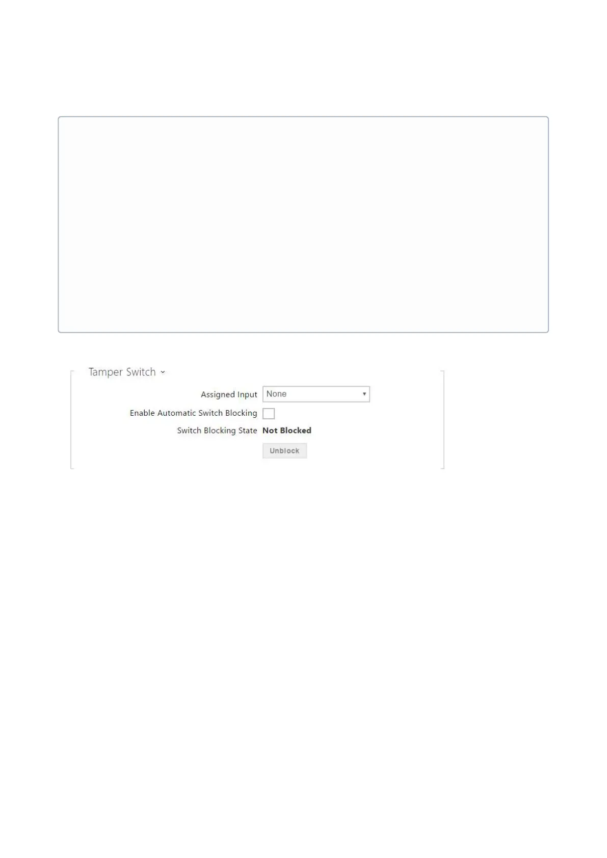
Assigned input–select the logic input to which the tamper switch is to be
connected.TamperSwitchActivatedsignals the tamper switch activation.
Enable automatic switch blocking– block the switches by tamper activation for 30
minutes.
Switch blocking state–display and make switch blocking settings.
•
Note
Secured state signalling is typically used with an access control controller connected
to one of the intercom digital inputs. The wire leading from the PBX is connected to
the intercom directly or via an extending module. The secured state LED location is
variable depending on the intercom type:
The 2N
®
IP Vario(91371…U) intercoms are equipped with a red LED indicator
located in the middle of the backlit name tags.
The2N
®
IP Forceintercoms are equipped with a red LED indicator located in the
integrated card reader window.
The2N
®
IP Versointercoms are equipped with a red padlock pictogram in the left-
hand upper corner of the basic module.