Configuration manual for 2N IP intercoms
•
•
•
•
•
•
Associated Switch–set the switch to be activated after user authentication via this
module. If you set Door Lock Switch, the authentication rules specified in Hardware / Door
will be used.
Signal Range – set the signal range (5 = maximum, 1 = minimum), i.e. the distance over
which the Bluetooth module can communicate with a mobile phone. It is recommended
that the actual signal range is tested while setting, as it is affected by a number of factors
(installation layout, mobile phone type and position in particular).
Launch Authentication By–set the authentication method for a mobile phone:
Tap in App– authentication has to be confirmed by tapping on an icon in the
application running in a mobile phone.
Interacting With Device – touch the card reader having a phone with paired
2N
®
Mobile Keyto confirm authentication.
Motion Detection –authentication will be launched by motion detection via a
phone with the paired 2N
®
Mobile Keyapplication.
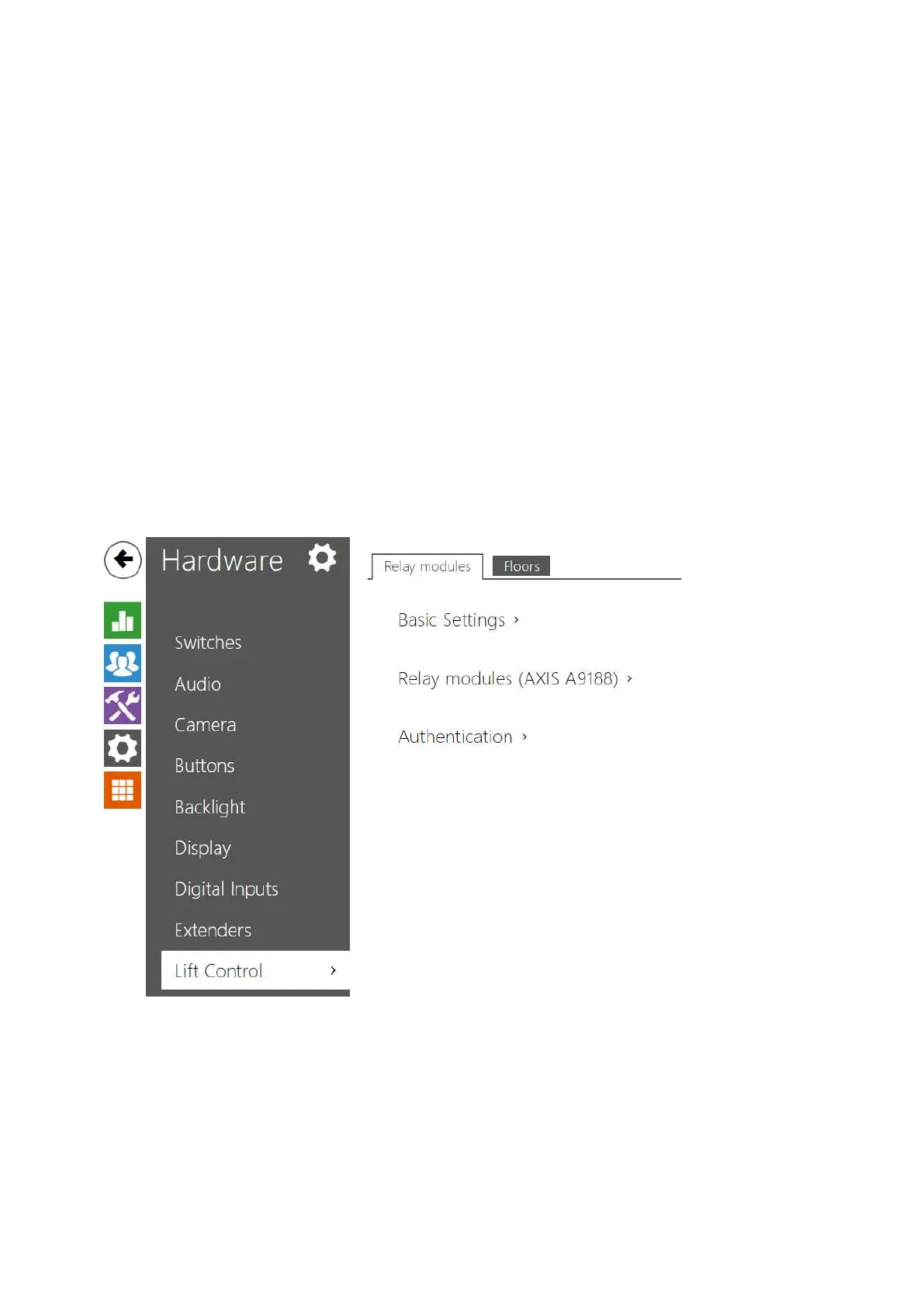
5.5.10 Lift Control
To control the floor lift access, connect the AXIS A9188 relay module to the 2N IP intercom
(2N
®
IP Style,2N
®
IP Verso,2N
®
IP Force,2N
®
IP Safety,2N
®
IP Vario). Up to 8 relay modules
can be connected to one 2N IP intercom, each of which can control up to 8 floors, which makes a
total of 64.