12000 Pecos Street, Suite 290, Westminster, CO 80234 | www.3xlogic.com | (877) 3XLOGIC
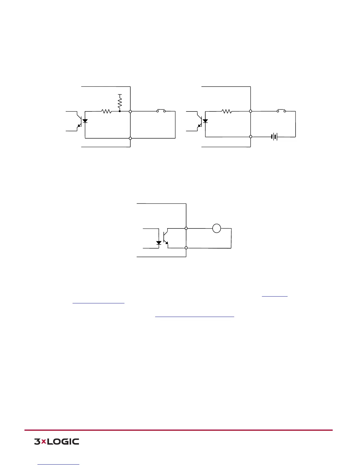
1). Sensor (DI) connection: Sensor (DI) can be connected to either a voltage type sensor or a relay type
sensor as the following figures. Settings can be done through the camera’s webpage.
Input voltage range: 0VDC minimum to 5VDC maximum, Max 50mA.
CAUTION: Do not exceed the maximum input voltage or relay rate.
2). Alarm (DO) Connection: Only the relay type is supported.
Relay Rating: Max 24VDC 50mA
CAUTION: Do not exceed the maximum relay rating.
3). LAN Connection: This is a RJ45 LAN connector for 10/100 Base-T Ethernet. Use the Ethernet cable
(RJ45. to connect the device to a hub or a router in the network. Refer to Section 6: Power over
Ethernet Specifications to for further detail.
4). Power Connection: The camera can be powered from either 12VDC or PoE. If the camera is
powered via PoE, refer to Section 6: Power over Ethernet Specifications for further detail.