Hardware and Installation Manual| VISIX V-Series All-in-One Cameras – Gen I
12000 Pecos Street, Suite 290, Westminster, CO 80234 | www.3xlogic.com | (877) 3XLOGIC
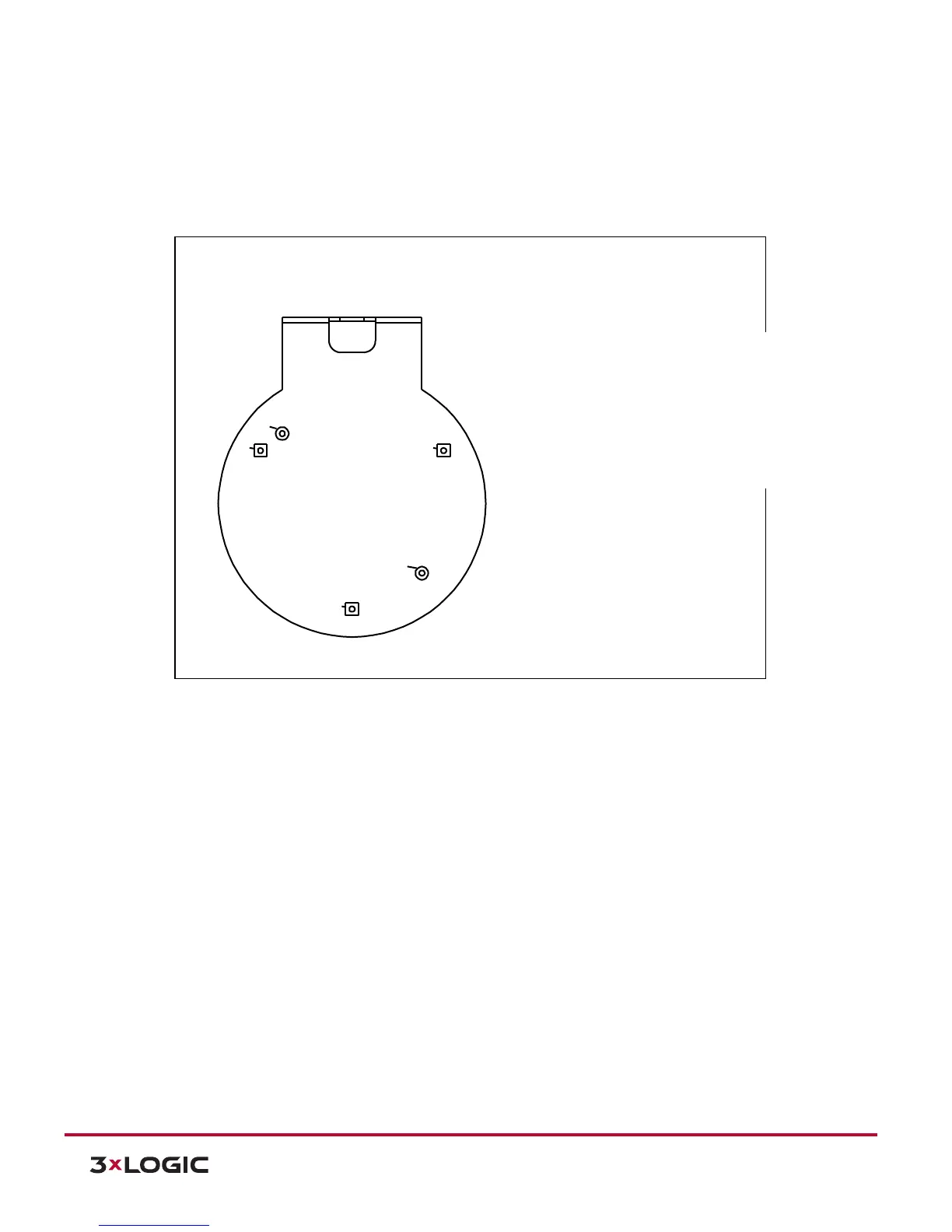
4.8.2 LOCATION OF THE HOLES FOR M3X6L BOLTS
The image below shows which spots the camera should be attached to on the wall mount bracket (VX-
2AIMD-CM).
1). Identify the location of the holes with the alphabet letter, B, on the bracket, and insert the
M3x6L bolts in the holes to attach the camera.
W M B - 3202/C M B -3202
This guid e illustra tes ho w to assem ble the co rner m ount adapter and
p ole m o unt ad ap ter.
C heck the letter of the alp habet assigned to each adapter and tighten
the screw s in the corresp onding holes to assem b le the adapter.
A - A - A (M 3TA P )
A
B
B
A
A
IPN 3202H D
B - B (M 3TA P )
IPN 302H D