12000 Pecos Street, Suite 290, Westminster, CO 80234 | www.3xlogic.com | (877) 3XLOGIC
6.5.3 LAN CONNECTOR
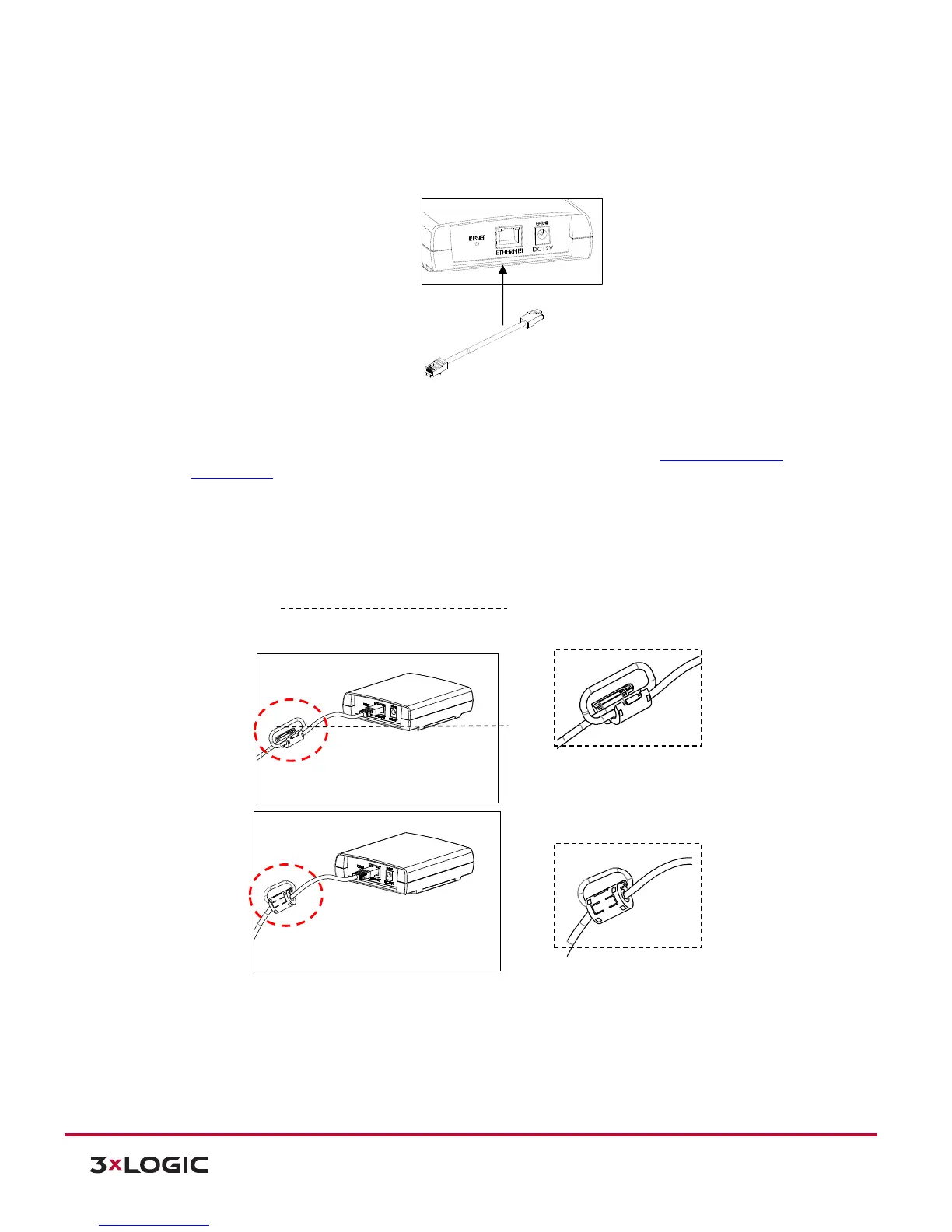
3). Connect the main unit to the network using an Ethernet cable (RJ45). Then, install the ferrite core
on the Ethernet cable. Refer to the explanations below for the ferrite core installation.
NOTE: In case you intend to turn on the device by using the LAN cable, a PoE switch should be
available in your network. For more information about PoE, refer to Section 7: Power over Ethernet
Specifications for more information.
NOTE: Installing the provided ferrite core is highly recommended to reduce high frequency electrical noise
level. Here below are the instructions to install the ferrite core on the Ethernet cable.
Steps:
1). Open the ferrite core by lifting the clip.
2). Make one loop with the cable through the ferrite core. (See the enlarged image above.)
Close the ferrite core to hold the cable loop in the ferrite core’s chamber.
6.5.4 POWER CONNECTOR
4). Connect a DC12V power adaptor to the power connector on the main unit. If the camera is
powered on via PoE, a power adaptor is not necessary to be connected to the main unit.
NOTE: Please make sure that the camera unit needs to be connected to the main unit prior to the
power connection. Otherwise, the camera may fail to show image.