12000 Pecos Street, Suite 290, Westminster, CO 80234 | www.3xlogic.com | (877) 3XLOGIC
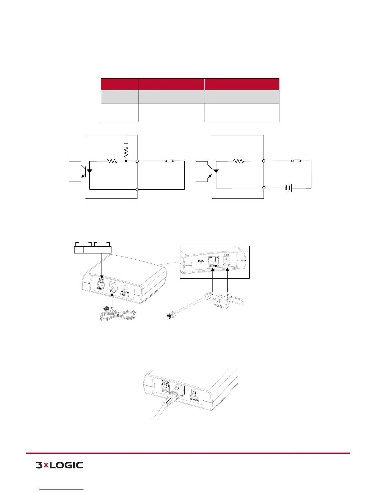
DI Sensor: It is used for connecting a device such as a PIR and a door/window sensor.
Refer to the table below for electrical wiring information:
Then, the connected device can be activated via its webpage.
6.5.2 CAMERA CONNECTOR
2). Connect the camera unit to the main unit by inserting the camera’s DIN connector to the camera’s
connector on the main unit by placing the arrow mark to be shown upward like the image below.
NOTE: Please make sure that the camera unit needs to be connected to the main unit prior to the
power connection. Otherwise, the camera may fail to show image.