Hardware and Installation Manual| VISIX V-Series All-in-One Cameras – Gen I
12000 Pecos Street, Suite 290, Westminster, CO 80234 | www.3xlogic.com | (877) 3XLOGIC
4.8 Compatible Accessory Installation (Mounts)
The compatible accessories to mount this camera model are as follows.
Model Names & Combinations
VX-2AIMD-CM
VX-2AIMD-WM
VX-2AIMD-CM + VX-2AIMD-PMC
VX-2AIMD-GB
The installation instructions for each bracket are contained within the proceeding sections of this manual.
Model Image
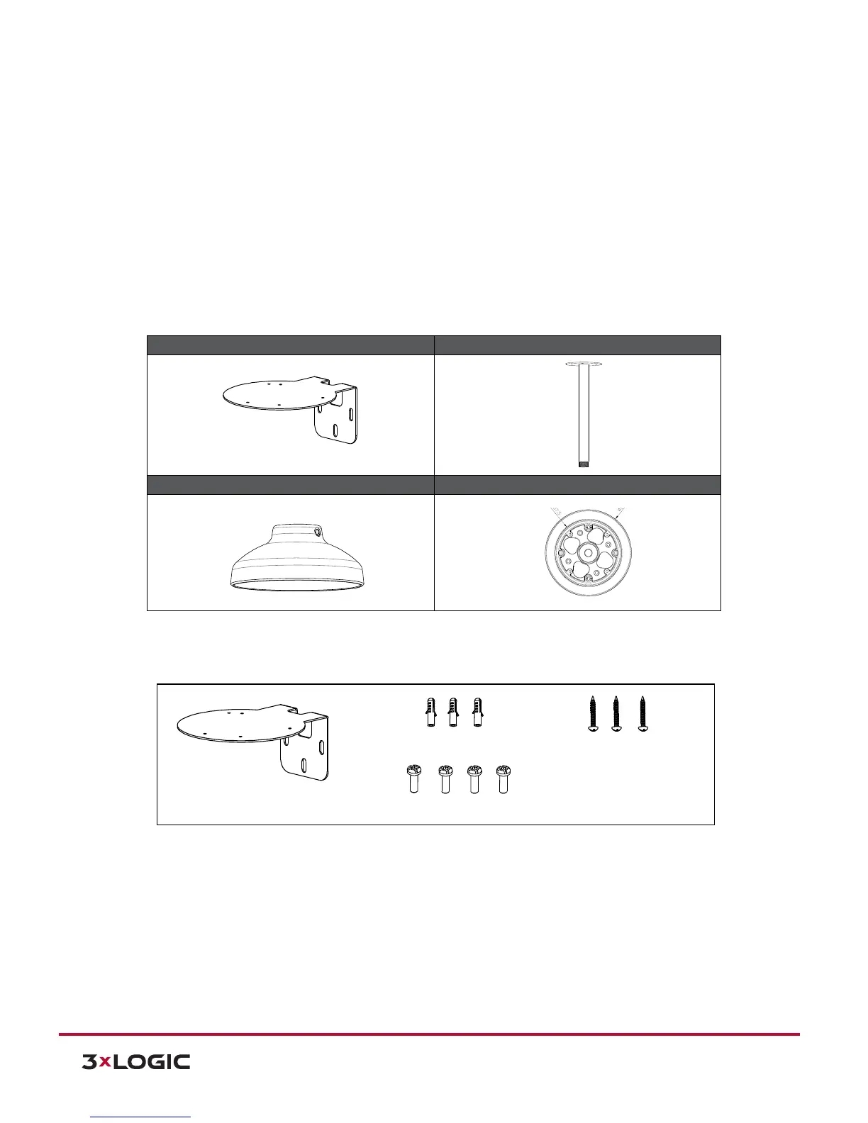
4.8.1 WALL MOUNT - VX-2AIMD-WM
Contents
W M B - 3202/C M B - 3202
This g uid e illustra te s how to a ssem b le the corner m ount adapter and
po le m ount adapter.
C h eck th e letter of the alp habet assigned to each ad apter and tig hten
the screw s in the corresp ond ing ho les to assem ble the adapter.
A - A - A (M 3TA P)
M O D E L : IP N 3202H D
B - B (M 3TA P )
M O D E L : IP N 302H D
A
A
B
B
A
W M B - 3202/C M B - 3202
This g uid e illustra tes ho w to a ssem b le the corner m ount adapter and
po le m o unt ad apter.
C heck the letter o f the alph ab et a ssigned to each adapter and tighten
the sc rew s in the co rresp o nd ing ho les to assem ble the adap ter.
A - A - A (M 3TAP )
M O D E L : IP N 3202H D
B - B (M 3TAP )
M O D E L : IP N 302H D
A
A
B
B
A
W M B - 3202/C M B - 3202
This g uid e illustra tes ho w to a ssem b le the corner m ount adapter and
po le m o unt ad apter.
C heck the letter o f the alph ab et assigned to each adapter and tighten
the sc rew s in the co rrespo nd ing ho les to assem ble the adap ter.
A - A - A (M 3TAP )
M O D E L : IP N 3202H D
B - B (M 3TAP )
M O D E L : IP N 302H D
A
A
B
B
A
W M B - 3202/C M B -3202
This gu id e illu strates ho w to assem ble th e co rner m ou nt adapter and
p ole m o unt ad ap ter.
C he ck the letter of the alp hab et assign ed to each ad apter and tighten
the screw s in the corresp on ding holes to assem b le the ad apter.
A - A - A (M 3TA P )
A
B
B
A
A
IP N 3202H D
B - B (M 3TA P )
IP N 302H D
W M B - 3202/C M B -3202
This g uid e illustrate s ho w to assem ble th e co rn er m o unt adapter and
p ole m o unt ad ap ter.
C heck the letter of the a lp ha be t assig ned to ea ch ad apter and tig hten
the screw s in the co rre spo nd ing h oles to asse m ble the ad apter.
A - A - A (M 3TA P )
A
B
B
A
A
IP N 32 02H D
B - B (M 3T A P )
IP N 302H D