10
MODGAS-XWR2 Technical Guide
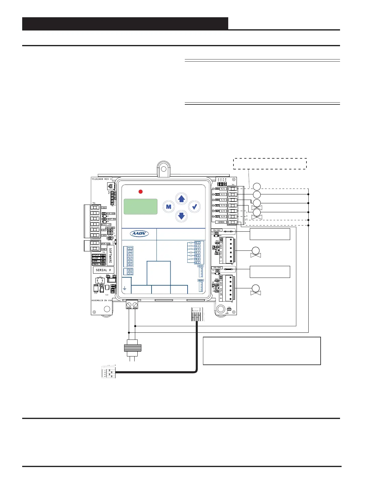
STAND-ALONE WIRING
Secondary Board 2V2IGN2S
In this conguration, the wiring on Figure 3, page 9 is the
primary portion and Figure 4, this page is the secondary portion,
creating four modulating valves as two stages.
If using an MHGRV-X Module along with the secondary
MODGAS-XWR2 in Stand-Alone Mode, the SAT Sensor always
attaches to the Primary MODGAS-XWR2.
Figure 4: Stand-Alone Wiring - Secondary Board 2V2IGN2S
Fan Enable
Low Speed Fan
Modulating
Gas Valve 3
(Slave to Mod
Gas Valve 1)
Proof of Ignition
Signal 3 (24 VAC)
Heat Valve 1
Check your Fan Relay Wiring (RLY1)
Schematic for proper wiring.
Heat Valve 2
Fixed Heat Stage 5
Fixed Heat Stage 6
ALARM
UP
DOWN
ENTERMENU
MODGAS-XWR2
AAON P/N:ASM01695
LABEL P/N:
G041530
E-BUS
DUAL
I2C
CONNECT
+24 VAC
GND
@ 24 VAC
1 AMP MAX
CONTACT
RATING IS
COMMON
RELAY
OUTPUTS
GAS VALVE
TERMINALS
GAS
VALVE 1
GAS
VALVE 2
INPUT TERMINALS (TYPE)
HEAT ENABLE (BI)
AUX. (BI)
GND
RESET IN (AI)
SAT IN (AI)
GND (AI)
GND
AUX. (AI)
www.aaon.com
LOW SPEED
HEAT 1
HEAT 2
HEAT 3
HEAT 4
PROOF OF IGNITION 1
PROOF OF IGNITION 2
FAN
Notes:
1. 24 VAC must be connected so that all ground wires
remain common.
2. All wiring to be in accordance with local and national
electrical codes and specifications.
E-BUS cable connects to the
primary MODGAS-XWR2.
GV3
CR3
CR4
H1
Line
40 VA
transformer
minimum
GND
18-30
VAC
H2
Proof of Ignition
Signal 4 (24 VAC)
GV4
Modulating
Gas Valve 4
(Slave to Mod
Gas Valve 2)
NOTE: Up to two additional xed heat stages can be
congured by using Heat 3 (RLY5) and Heat 4
(RLY6). Up to 12 additional xed stages can be
added by using the 12 Relay E-BUS Expansion
Module. (Figure 8, page 14).

 Loading...


