15
MODGAS-XWR2 Technical Guide
COMMUNICATIONS WIRING
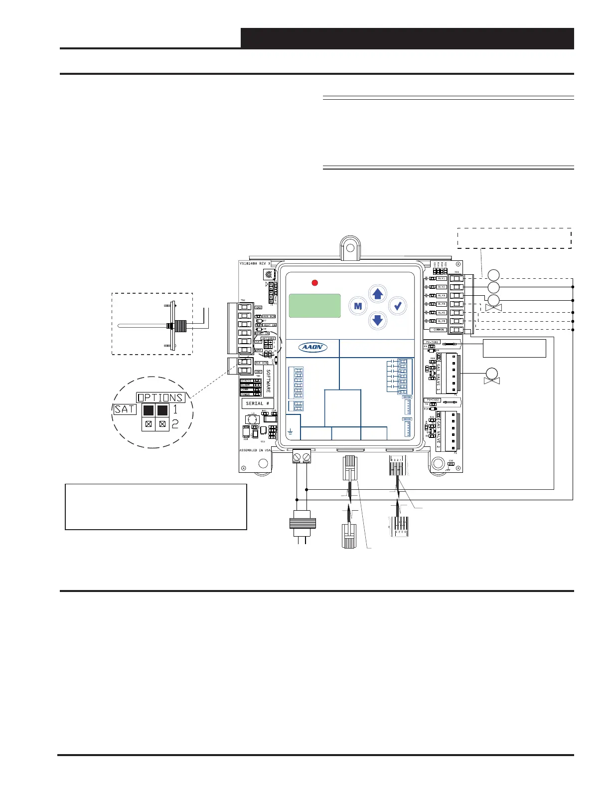
One Modulating Valve, One Ignitor, One Stage (1V1IGN1S)
This conguration is used to control one modulating valve, which
must be placed on Gas Valve 1 (attached to Heat 1 (RLY3)).
For VCM-X Controllers, use an I
2
C cable connecting to the
appropriate I
2
C port on the controller.
For all other controllers, use an E-BUS cable connecting to an
E-BUS port on the controller.
Figure 9: Communications Wiring - One Modulating Valve, One Ignitor, One Stage
NOTE: Up to three additional xed heat stages can be
configured by using Heat 2 (RLY4), Heat 3
(RLY6), and Heat 4 (RLY6). If additional xed
stages are required, these should be congured
and wired to the AAON unit controller’s relays.
Fan Enable
Low Speed Fan
Modulating
Gas Valve 1
Proof of Ignition
Signal 1 (24 VAC)
Heat Valve 1
Check your Fan Relay Wiring (RLY1)
Schematic for proper wiring.
Fixed Heat Stage 2
Fixed Heat Stage 3
Fixed Heat Stage 4
ALARM
UP
DOWN
ENTERMENU
MODGAS-XWR2
AAON P/N:ASM01695
LABEL P/N:
G041530
E-BUS
DUAL
I2C
CONNECT
+24 VAC
GND
@ 24 VAC
1 AMP MAX
CONTACT
RATING IS
COMMON
RELAY
OUTPUTS
GAS VALVE
TERMINALS
GAS
VALVE 1
GAS
VALVE 2
INPUT TERMINALS (TYPE)
HEAT ENABLE (BI)
AUX. (BI)
GND
RESET IN (AI)
SAT IN (AI)
GND (AI)
GND
AUX. (AI)
www.aaon.com
LOW SPEED
HEAT 1
HEAT 2
HEAT 3
HEAT 4
PROOF OF IGNITION 1
PROOF OF IGNITION 2
FAN
See SAT OPTIONS Tables for Jumper Settings.
Only one Supply Air Temperature Sensor can be
used per application.
Notes:
1. 24 VAC must be connected so that all ground wires
remain common.
2. All wiring to be in accordance with local and national
electrical codes and specifications.
GV1
CR1
CR2
H1
Line
40 VA
transformer
minimum
Supply Air
Temperature
Sensor
Mount in unit
supply air duct
GND
18-30
VAC
Connect Supply Air Temperature Sensor
to AI2 (VCM-X and VCB-X) or AI3
(VCCX2) and GND on main controller
I
2
C cable connects to the VCM-X
E-BUS Controller's expansion
port
E-BUS cable connects to the
VCCX2 or VCB-X Controller's
expansion port

 Loading...


