20
MODGAS-XWR2 Technical Guide
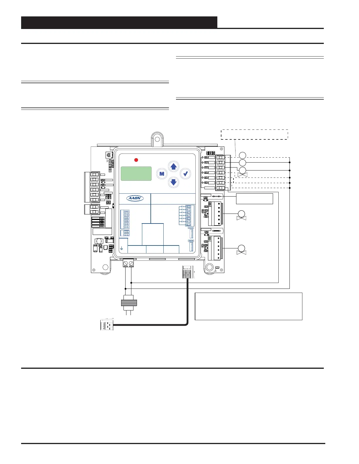
COMMUNICATIONS WIRING
Secondary Board - 2V1IGN1S
Figure 14: Stand-Alone Wiring - Secondary Board 2V1IGN1S
Fan Enable
Low Speed Fan
Proof of Ignition
Signal 2 (24 VAC)
Heat Valve 2
Check your Fan Relay Wiring (RLY1)
Schematic for proper wiring.
ASSEMBLED IN USA
U15
D13
R
R
R
R
L1
R61
C28
SERIAL #
POWER
COMM
ALARM
STATUS
TB3
GND
AUX AIN
J3
GND
1
2
SAT
OPTIONS
RESET IN
D8
HEAT EN
D7
AUX BIN
GND
J1
U1
TB2
R1
YS102408 REV 3
TB1
RLY1
RLY2
RLY3
RLY4
RLY5
RLY6
COMMON
PO-IGN1
P3
D9
R33
R1
P1
PO-IGN2
P4
D10
R36
R2
Q2
R5
P2
C35
.01UF
R8
R22
R18
R16
R12
R13
R42
R44
D14
SOFTWARE
C22
C27
GAS VALVE 2
GAS VALVE 1
ALARM
UP
DOWN
ENTERMENU
MODGAS-XWR2
AAON P/N:ASM01695
LABEL P/N:
G041530
E-BUS
DUAL
I2C
CONNECT
+24 VAC
GND
@ 24 VAC
1 AMP MAX
CONTACT
RATING IS
COMMON
RELAY
OUTPUTS
GAS VALVE
TERMINALS
GAS
VALVE 1
GAS
VALVE 2
INPUT TERMINALS (TYPE)
HEAT ENABLE (BI)
AUX. (BI)
GND
RESET IN (AI)
SAT IN (AI)
GND (AI)
GND
AUX. (AI)
www.aaon.com
LOW SPEED
HEAT 1
HEAT 2
HEAT 3
HEAT 4
PROOF OF IGNITION 1
PROOF OF IGNITION 2
FAN
Notes:
1. 24 VAC must be connected so that all ground wires
remain common.
2. All wiring to be in accordance with local and national
electrical codes and specifications.
E-BUS cable connects to the
primary MODGAS-XWR2.
GV3
CR3
CR4
H1
Line
40 VA
transformer
minimum
GND
18-30
VAC
GV4
Fixed Heat Stage 5
Fixed Heat Stage 6
Fixed Heat Stage 7
Modulating
Gas Valve 3
Modulating
Gas Valve 4
In this conguration, the wiring on Figure 13, page 19 is the
primary portion and Figure 14, this page is the secondary
portion, thus creating four modulating valves as one stage.
NOTE: The Four Modulating Valves Primary/Secondary
conguration is not supported when using I
2
C
communications.
NOTE: Up to three additional xed heat stages can be
configured by using Heat 2 (RLY4), Heat 3
(RLY6), and Heat 4 (RLY6). If additional xed
stages are required, these should be congured
and wired to the AAON unit controller’s relays.