42
MODGAS-XWR2 Technical Guide
Replacing the MODGAS-XWR with the
MODGAS-XWR2
The retrot replacement involves a few easy steps. Refer to
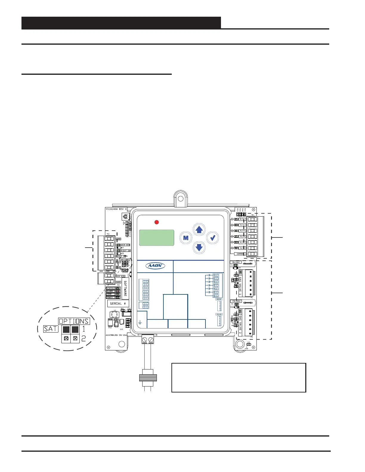
Figure 18, this page.
Step 1: Disconnect power from the MODGAS-XWR module.
Step 2: Set the SAT Options Jumper to the same settings as
before.
Step 3: The Supply Air Temperature Sensor needs to remain
installed on whatever controller it is currently on.
Step 4: Unplug the TB2 input terminal block from the
MODGAS-XWR and replug it into the MODGAS-
XWR2 board.
Step 5: Unplug the Ignition blocks and Valve headers from the
MODGAS-XWR and replug them into the MODGAS-
XWR2 board.
Step 6: Wire the MODGAS-XWR2 relays according to the
valve conguration you will be using.
Step 7: Connect power to the MODGAS-XWR2.
Step 8: Congure the MODGAS-XWR2 using the
LCD Display Screens.
Figure 18: MODGAS-XWR2 Module
APPENDIX B: MODGAS-XWR REPLACEMENT
MODGAS-XWR2 Replacement of MODGAS-XWR
STEP 2
STEP 4
STEP 5
STEP 6
ALARM
UP
DOWN
ENTERMENU
MODGAS-XWR2
AAON P/N:ASM01695
LABEL P/N:
G041530
E-BUS
DUAL
I2C
CONNECT
+24 VAC
GND
@ 24 VAC
1 AMP MAX
CONTACT
RATING IS
COMMON
RELAY
OUTPUTS
GAS VALVE
TERMINALS
GAS
VALVE 1
GAS
VALVE 2
INPUT TERMINALS (TYPE)
HEAT ENABLE (BI)
AUX. (BI)
GND
RESET IN (AI)
SAT IN (AI)
GND (AI)
GND
AUX. (AI)
www.aaon.com
LOW SPEED
HEAT 1
HEAT 2
HEAT 3
HEAT 4
PROOF OF IGNITION 1
PROOF OF IGNITION 2
FAN
GND 18-30 VAC
Line
40 VA
Transformer
Minimum
1. 18-30 VAC must be connected so that all ground
wires remain common.
2. All wiring to be in accordiance with local and
national electrical codes and specifications.
 Loading...


