14
MODGAS-XWR2 Technical Guide
STAND-ALONE WIRING
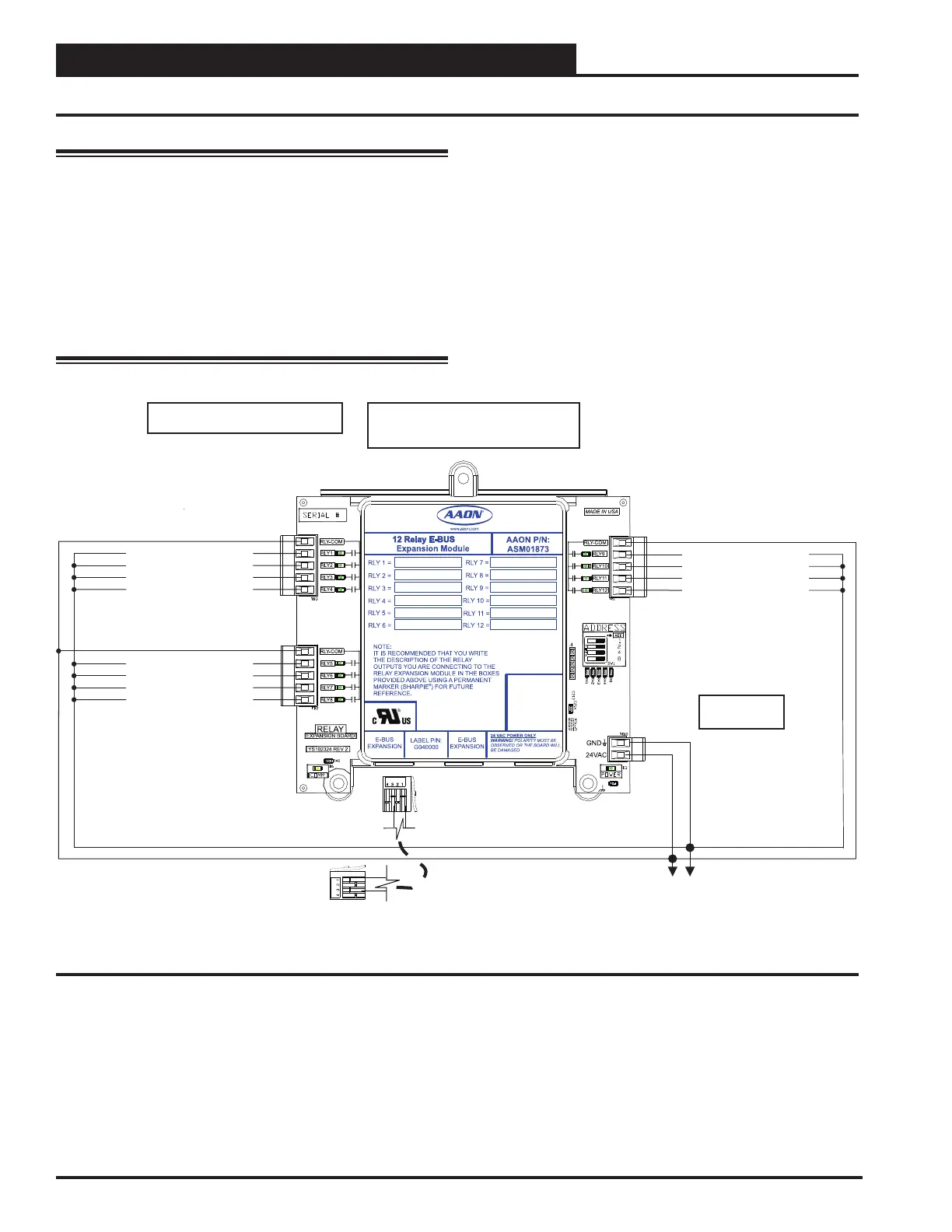
12 Relay E-BUS Expansion Module
Figure 8: Stand-Alone Wiring - 12 Relay E-BUS Expansion Module
WARNING: Observe Polarity. All boards must be wired
with GND-to-GND and 24 VAC-to-24
VAC. Failure to observe polarity will result
in damage to one or more of the boards.
Expansion modules must be wired in such
a way that the expansion modules and the
controller are always powered together. Loss
of power to the expansion module will cause
the controller to become inoperative until
power is restored to the expansion module.
Note: n = Number of fixed heat stages
configured on MODGAS-XWR2.
Fixed Heat Stage n + 1
18-30 VAC
GND
18-30
VAC
GND
15 VA minimum
power required
E-BUS cable connects to a
MODGAS-XWR2 or E-BUS
Adapter Hub
Fixed Heat Stage n + 2
Fixed Heat Stage n + 3
Fixed Heat Stage n + 4
Fixed Heat Stage n + 5
Fixed Heat Stage n + 6
Fixed Heat Stage n + 7
Fixed Heat Stage n + 8
Fixed Heat Stage n + 9
Fixed Heat Stage n + 10
Fixed Heat Stage n + 11
Fixed Heat Stage n + 12
Note: All relay outputs are normally open
and rated for 24 VAC power only.
1 amp maximum load.

 Loading...


