29
MODGAS-XWR2 Technical Guide
HEAD1 TEXT
Head 2 Text
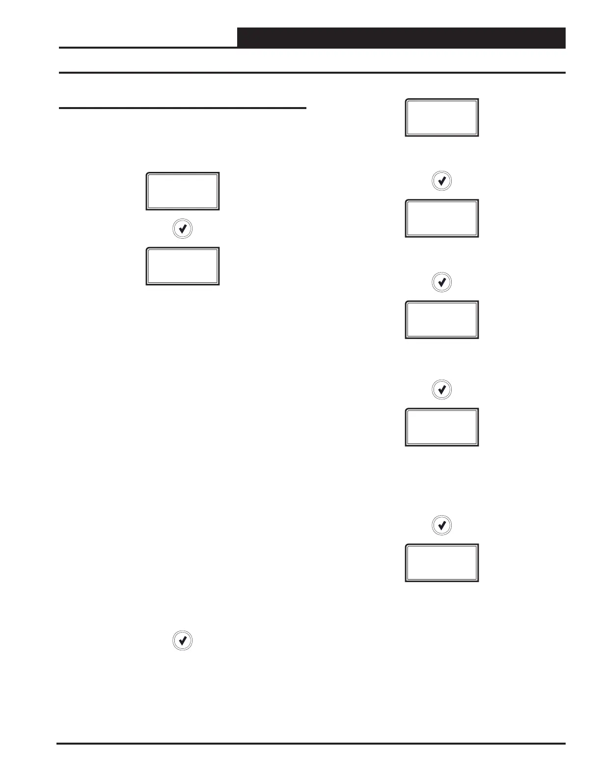
Status Screens
Refer to the following map when navigating through the Status
Screens. From the STATUS Screen, press <ENTER> to scroll
through the screens.
STATUS
MODE STATE
This screen displays the current mode of operation. They are as
follows:
OFF_MODE: This mode will display when there is no call for Heat
and Heating has been disabled. All relays are o, all xed stages are
o, and the valves are moved to the home position. This is the default
mode.
IGNITE_MODE: Each time Heat is activated, the unit will rst go into
Ignition Mode. During this mode, the valve moves to the start position
and Stage 1 is ignited. Once Proof of Flame (POF) is established, the
unit will go into Heat. Proof of Flame is established when the POF
signal has been present for the ignition hold time. The ignition position
and proof of ame time can both be set in the hidden conguration
screen.
FORCE_MODE: If the valves are being forced for testing, the board
moves into this mode. This mode maintains the normal heating
sequence for each modulation conguration, but instead of using the
PID Loop it uses the forced position (set from either the Force Menu
or through Modbus). After 10 minutes of no keypad input, the Force
Mode will disengage.
VCMX_EOL: If the module is being tested for the VCM-X via I
2
C
communications, then the module moves into this mode.
MOD HEAT STAGE ##: After Ignition Mode, the unit will enter the
Heat Mode and will begin to modulate the gas valve(s) to maintain the
Heating Supply Air Setpoint. Once the call for heat goes away, the unit
will leave the Heat Mode.
SLAVE_HEATING: If the module is secondary to another MODGAS-
XWR2, then this mode replaces Modulate Mode. If the board is in this
mode, then that means there is a MASTER XWR2 board running the
PID Loop control. A secondary module in this mode simply mimics the
operation of the MASTER XWR2 board.
TEST_MODE: If the module is being tested through Prism, the
module will move into this mode to operate (e.g. turn relays on/o).
VALVE 1
100%
VALVE 1 POSITION
0% to 100% or Closed
VALVE 2
100%
VALVE 2 POSITION
0% to 100% or Closed
SA TEMP
XX.X
SUPPLY AIR TEMPERATURE
40ºF to 150ºF or 4ºC to 65ºC.
If no sensor is detected, screen will display “NO SENSR”
ACTIV SP
XX.X
ACTIVE SUPPLY AIR SETPOINT
Calculated from SAT Setpoint and Reset Setpoint in Stand-Alone
Mode. In Communications Mode, the main controller sends the
setpoint.
The SAT Setpoint is set by the LCD Display in Stand-Alone Mode
and is set by the main controller in Communications Mode.
FAN SPEED
OFF
FAN SPEED STATUS
Low, High, O
 Loading...


