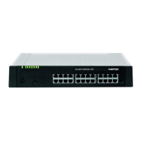
Ascotel® IntelliGate® 150/300 as of I7.9
Expansion Stages and System Limits 25
syd-0210/1.7 – I7.9 – 12.2009
3. 2. 1 Interfaces
The following mainboard interfaces can be accessed only when the housing cover
of the basic system is open:
Tab. 2 Mainboard
The following mainboard interfaces are routed to the front panel:
Tab. 3 Front panel
The diagram below shows the position of all the interfaces and slots on the main-
board and front panel.
Interfaces A150 A300 Designation / Remarks
Slots for interface cards 2 4 IC1...IC4 / with snap mechanism
Slots for system modules, type 1 1 1 SM1 / three system modules, stackable
Slots for system modules, type 2 – 1
1)
1)
For future expansions
SM2 / three system modules, stackable
Slots for LAN switch modules 1 2 WA0...WAx / two slots per module
Slots for wiring adapters 2 4 WA1...WAx / one slot per wiring adapter
Interface for EIM card 1 1 EIM / card holder
Interface for fan
2)
2)
The fan is required only if the A300 is rack-mounted
– 1 FAN / 3-pin connector (A300 only)
Interfaces A150 A300 Note
AD2 terminal interfaces 2 4 RJ45 socket
a/b terminal interfaces 2 2 RJ45 socket
Ethernet interfaces 10/100BaseT, half/full-duplex
1)
1)
Full duplex only, if the connected switch-port is configured to "automatic".
2 2 RJ45 socket
RJ45 sockets on front panel, total 16 24 RJ45 socket
Audio input 1 1 3-pin jack socket
Supply input 1 1 2-pin supply socket
Mechanical user interface 1 1 Pilot key
Optical user interface 1 1 LED display

 Loading...