9
edortcelEHp
epyTmetsyS
citamotuA
erutarepmeT
noitasnepmoC
launaM
erutarepmeT
noitasnepmoC
seireS0067246-2130.ontraP013-0719.ontraP
smetsySpiD7682elbacilppatoN003-0719.ontraP
smetsySwolF0767elbacilppatoN003-0719.ontraP
metsySnoisremmI1982246-2130.ontraP013-0719.ontraP
–
Earth
Earth Stud (on case) –
see Fig. 4.1
Earth Stud
(on case) –
see Fig. 4.1
Channel 1 Channel 2 Power
Supply
Retransmission Relay 1
Relay 2
Serial/Modbus
(If fitted)
12 34567 +– NL
Serial/Modbus
or 2
nd
Retrans.
output
12 3
45 6
12 3
45 6
1
2
3
4
–
–
–
–
Electrode System Temperature Compensator
5
6
7
–
–
–
1
2
3
4
5
6
–
–
–
–
–
–
Rx+
Rx–
Tx+
Tx–
0V
+
–
Retrans.
Output
Relays
1
2
3
4
5
6
–
–
–
–
–
–
NC
C
NO
NC
C
NO
Relay 1
Relay 2
Mains Supply
N
L
–
–
Neutral
LIne
–
Output
RS422/
RS485
NC
C
NO
Normally Closed
Common
Normally Open
=
=
=
Coax Screen
See Table 4.1
2
nd
Retrans. output
(If fitted)
4 +ve
5 –ve
Channel 1 Channel 2 Power
Supply
Retrans. Relay 1
Relay 2
output
Glass (inner core)
Reference (black)
1
2
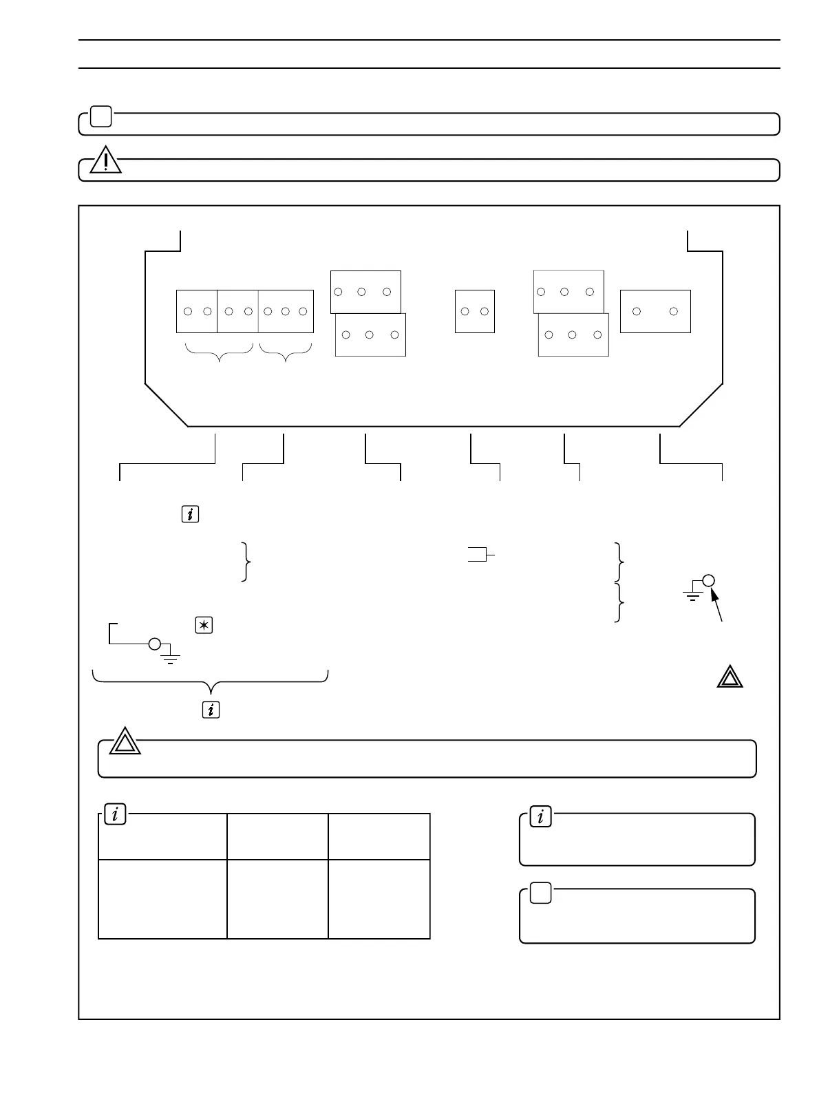
4 ELECTRICAL CONNECTIONS…
Warning. The power supply earth (ground) must be connected to ensure safety to personnel, reduction of the
effects of RFI interference and correct operation of the power supply interference filter terminal.
2
Information. The colours relate
to the multicore cable from the
electrode system – see Table 4.1.
✶
Note. When using 2867 Dip
Systems or Redox cartridge systems,
the screen is connected to terminal 4.
Refer also to Table 4.1 for connection details on different electrode types.
Fig. 4.4 Connections – Wall-/Pipe-mounted Instruments
4.3 Connections – Wall-/Pipe-mounted Instruments – Fig. 4.4
✶
Note. Refer to Fig. 4.1 for Access to Terminals.
Caution. Slacken terminal screws fully before making connections.
1