Do you have a question about the ABB 4690 and is the answer not in the manual?
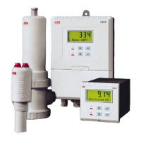
Describes the ABB Turbidity system, analyzer, and sensor components.
Details safety requirements for electrical equipment.
Explains common safety symbols found on equipment.
Highlights key points for safe operation and handling.
Provides guidance on proper disposal of electrical equipment.
Details the specifications and types of 7998 series turbidity sensors.
Illustrates system arrangements for analyzers and sensors.
Specifies environmental and physical placement requirements for analyzers and sensors.
Provides instructions for wall, pipe, and panel mounting the analyzer.
Details the mounting procedure and dimensions for the turbidity sensor.
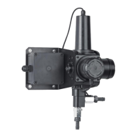
Guides on the mounting and setup of the optional de-bubbler unit.
Explains how to access terminals for wall/pipe-mount and panel-mount analyzers.
Contains crucial safety notes related to power supply, RFI, and wiring.
Details input/output connections for wall/pipe-mount and panel-mount analyzers.
Describes how to select the correct mains voltage for the analyzer.
Illustrates the wiring diagram for connecting the turbidity sensor.
Describes the components of the analyzer's digital display.
Explains the functions of the membrane keys for navigation and parameter adjustment.
Outlines the initial steps for starting up the analyzer.
Details how to operate the analyzer in turbidity measurement mode.
Provides guidelines for maintaining and checking secondary calibration standards.
Explains how to verify calibration using a dry standard.
Details the procedure for performing a wet (Formazine) calibration.
Explains how to access configuration settings using a security code.
Describes how to select the display language for the analyzer.
Guides on configuring sensor type, units, and display span.
Details configuration for alarm actions, set points, and retransmission.
Covers setting up baud rate, instrument identity, and parity.
Provides instructions and requirements for performing electrical calibration.
Offers guidance on cleaning sensors with and without wiper units.
Lists common error messages and their remedies.
Discusses causes and solutions for unstable or erratic turbidity readings.
Explains causes of spikes and how to mitigate them.
Lists maintenance kits with part numbers and contents.
Lists available accessories with part numbers and contents.
Lists available upgrade kits with part numbers and contents.
Lists essential spare parts with part numbers and contents.
Lists software EPROM options with part numbers.
Lists parts for the de-bubbler unit.
| Category | Measuring Instruments |
|---|---|
| Display | LCD |
| Measurement Type | Current, Voltage, Power, Frequency, Energy |
| Input Current | 1A or 5A AC |
| Protection Functions | Overcurrent, Overvoltage |