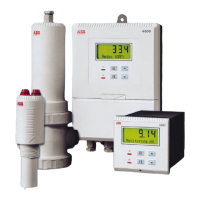
4690 Series
Turbidity systems 3Installation
8 IM/4690–EN Rev. A
3.3 Mounting the Turbidity Sensor
Systems and sensors are shown in Table 2.1 on page 3. The main components of each sensor are identified in Fig. 2.2 on page 4.
Referring to Figs 3.8 or 3.9:
1. Mount the sensor in the orientation shown using the bracket(s) provided, ensuring it is mounted within 5° of its vertical axis.
2. Connect the sample inlet and sample drain tubes.
3. Referring to Fig. 3.10, connect the sample outlet tube.
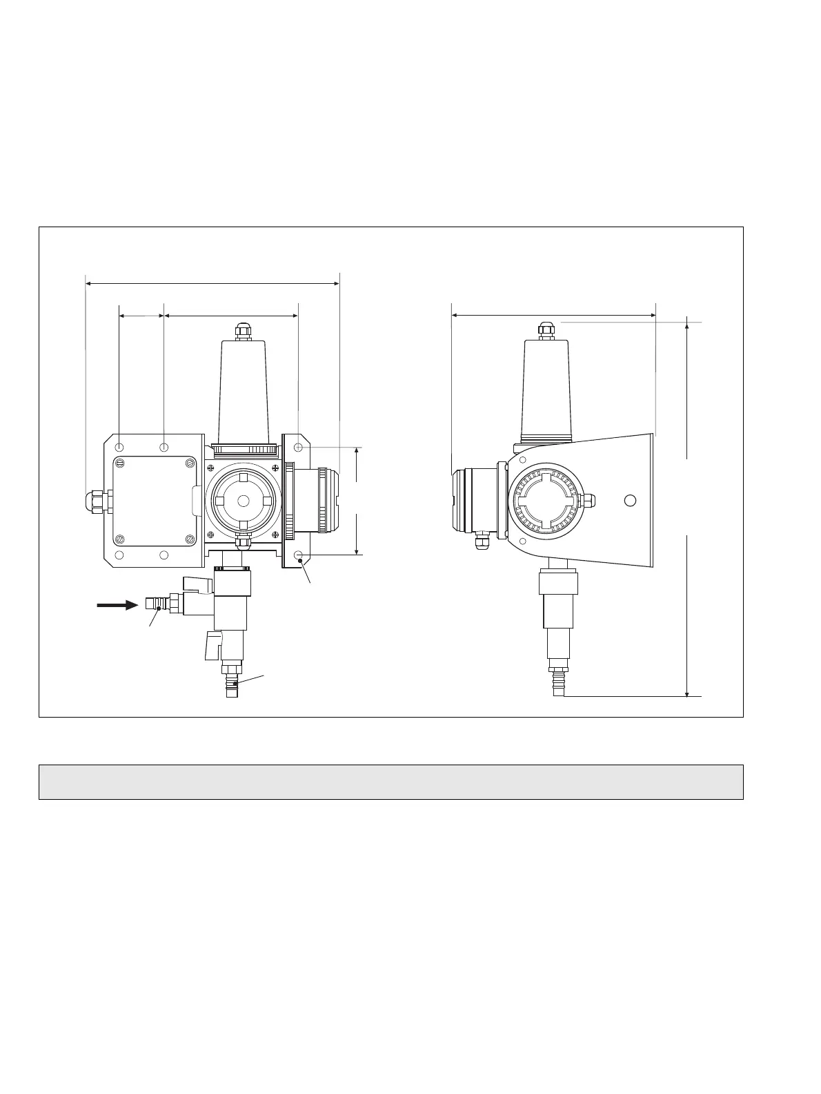
Dimensions in mm (in)
Fig. 3.8 Sensor Dimensions (With Optional Wiper Unit)
Note. Allow a further 30 mm (1.2 in) (approximately) clearance above the wiper unit for the bend in the wiper unit cable.
6 x Ø7 (0.3)
Mounting Holes
Sample Drain
Connector
(12 mm [0.5 in]
internal diameter)
Sample Inlet Connector
(12 [0.5] internal
diameter tube)
403.0
(17.0)
see
Note
below
298.0 (11.7)
230.0 (9.0)
118.0
(4.65)
155.5 (6.12)
46.5
(1.83)