4690 Series
Turbidity systems 3Installation
IM/4690–EN Rev. A 9
3.3.1 Sample Flowrate
Set a minimum flowrate of 0.5 l min
-1
to prevent solids settling in
the pipework. Increase the flowrate if necessary but do not
exceed the maximum flow rate of 1.5 l min
-1
.
When measuring turbidity, it is important that additional sources
of light scattering, such as gas bubbles in the sample, are
eliminated. An optional debubbler (part number 7997 500) is
available to eliminate gas bubbles – refer to Section 3.4,
page 10.
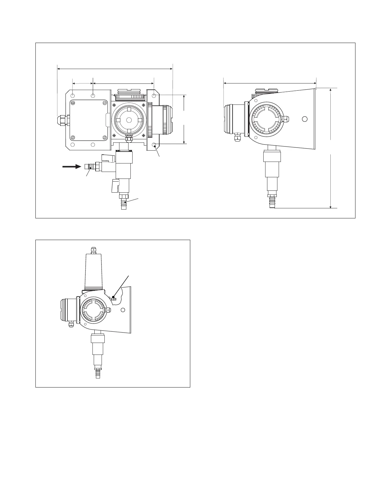
Dimensions in mm (in)
Fig. 3.9 Sensor Dimensions (Without Optional Wiper Unit)
6 x Ø7 (0.3)
mounting holes
Sample Drain
Connector
(12 mm [0.5 in] internal
diameter tube)
Sample Inlet Connector
(12 [0.5] internal
diameter tube)
298.0 (11.7)
230.0 (9.0)
282.0
(11.1)
118.0
(4.65)
155.5 (6.12)
46.5
(1.83)
Fig. 3.10 7998 Series – Sample Outlet Connector Location
Sample Outlet
Connector (6 [0.25]
internal diameter tube)