4690 Series
Turbidity systems 3Installation
6 IM/4690–EN Rev. A
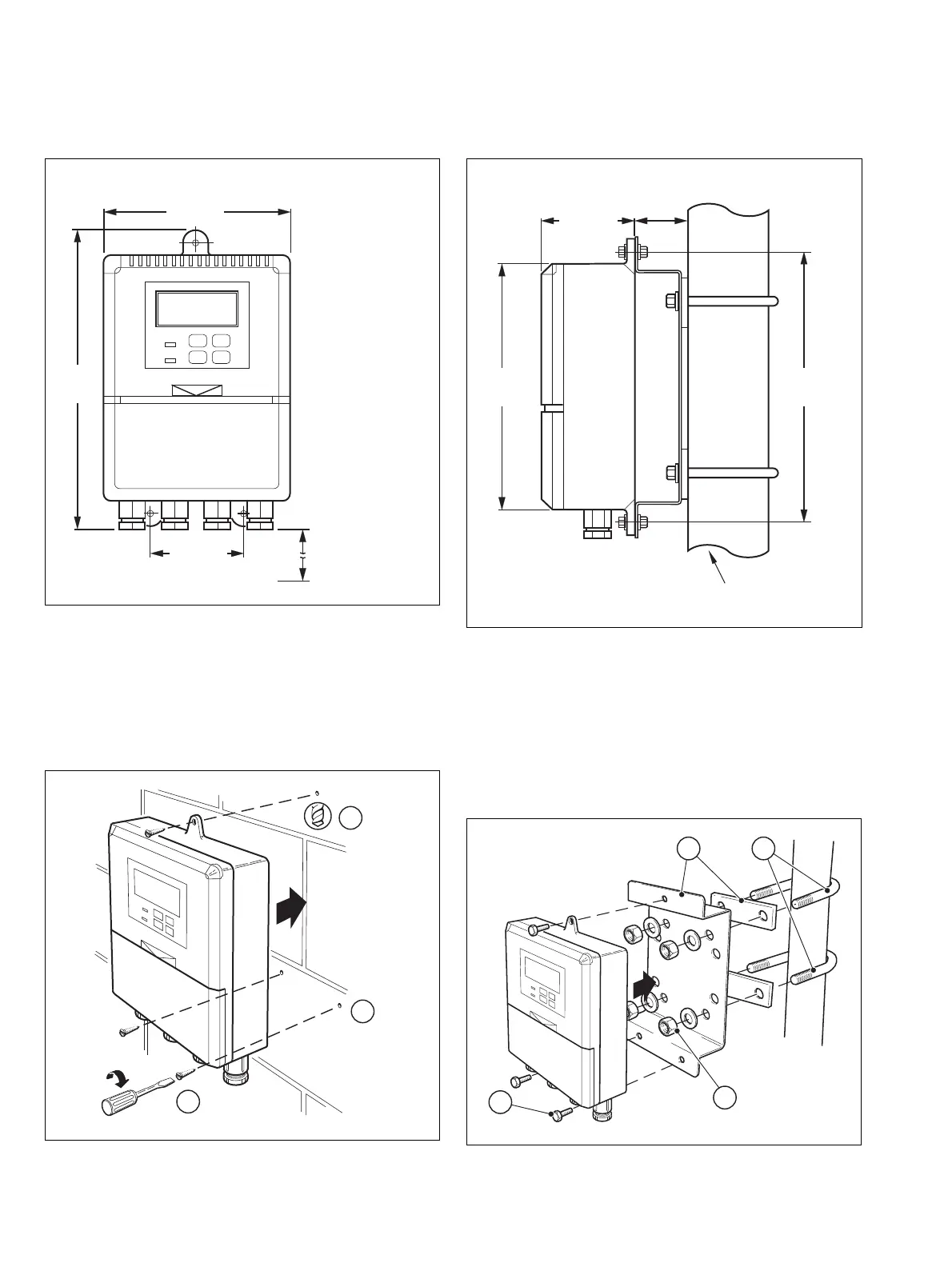
3.2 Mounting the Analyzer
3.2.1 Wall-mounting
Referring to Fig. 3.3:
a Mark fixing centers (see Fig. 3.2).
b Drill suitable holes.
c Secure analyzer to wall using suitable fixings.
3.2.2 Pipe-mounting
Referring to Fig. 3.5:
a Position 'U' bolts on pipe.
b Position plates over 'U' bolts.
c Secure plates.
d Secure analyzer to mounting plate.
Dimensions in mm (in.)
Fig. 3.2 Overall Dimensions
Fig. 3.3 Wall-mounting
160 (6.3)
69 (2.72)
200
(7.9)
250
(9.84)
Fixing Centers
Allowance for
Cable Bends
Dimensions in mm (in.)
Fig. 3.4 Overall Dimensions
Fig. 3.5 Pipe-mounting
68 (2.68)
42
(1.65)
232
(9.13)
214
(8.43)
Fixing Centers
61 (2
3
/8 O.D. Vertical or Horizontal Post)