4690 Series
Turbidity systems 3Installation
IM/4690–EN Rev. A 5
3 Installation
3.1 Siting Requirements
3.1.1 Analyzer 3.1.2 Turbidity Sensor
To enable the turbidity sensor to be removed easily for
maintenance, ensure an all-round clearance of 200 mm (7.9 in) –
see Section 3.3, page 8 for the overall dimensions of the sensor.
Caution.
Mount in a location free from excessive vibration.
Mount away from harmful vapors and dripping fluids.
Note. Mount the analyzer at eye level to enable an
unrestricted view of the front panel displays and controls.
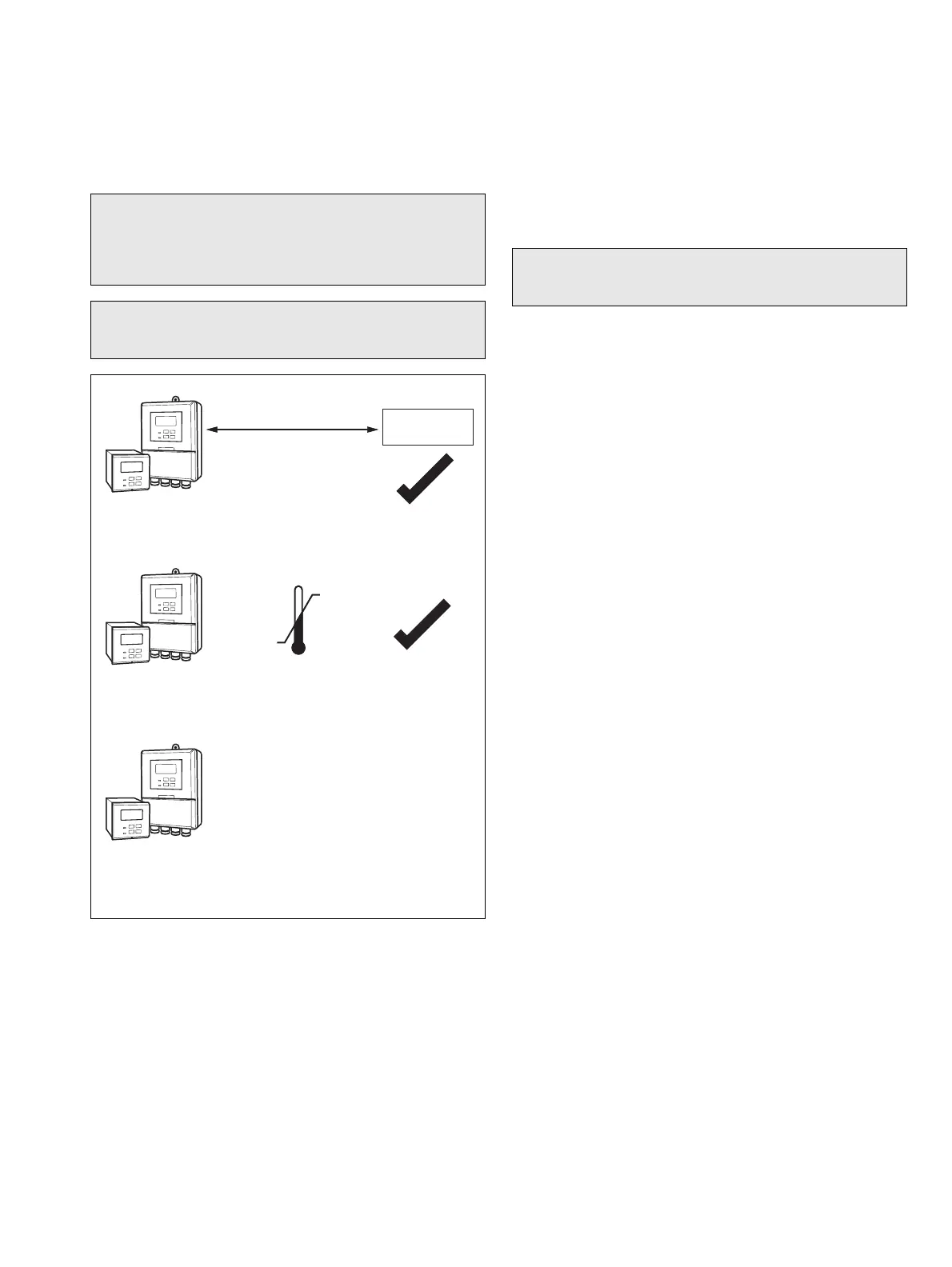
Fig. 3.1 Siting Requirements – Analyzer
A – Maximum Distance between Analyzer and Sensor
B – Within Temperature Limits
C – Within Environmental Limits
Maximum Distance
20 m (65.6 ft)
Turbid ity
Sensor
55 °C
(131 °F)
Max.
–20 °C
(–4 °F)
Min.
Note. Ensure the sensor is located at an appropriate height
to ensure ease of access during calibration and cleaning.