4690 Series
Turbidity systems 3Installation
IM/4690–EN Rev. A 11
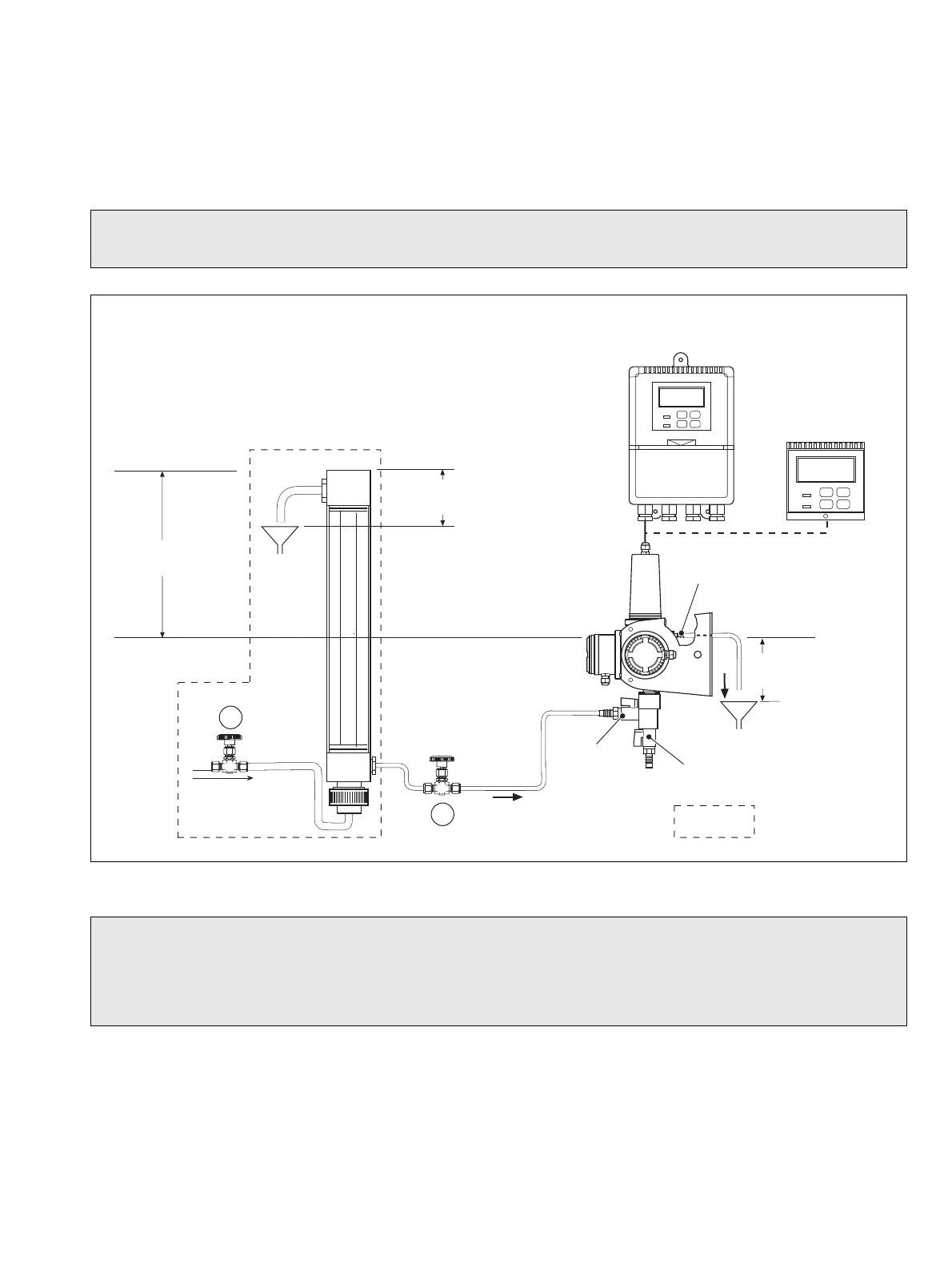
3.4.2 Set Up Procedure for De-bubbler
With a system that includes a de-bubbler, referring to Fig. 3.12:
1. Open the 'sample in' isolating valve
A such that the overflow from the de-bubbler is at a minimum.
2. Adjust the sample flow through the turbidity system using flow regulating valve B.
Note. Sample regulating valves together with a flow indicator are recommended to ensure easy maintenance and consistent
performance. These devices are not supplied with the 7998 Turbidity systems.
Dimensions in mm (in)
Fig. 3.12 Typical System Installation for 7998 Series Turbidity Systems
Caution.
1. To prevent degassing of the sample and very erratic readings, do not exceed this measurement.
2. This is the minimum installation distance that ensures adequate flowrate through the sensor. Increase this distance as
necessary if using long or small-bore tubing.
Sample In
Drain Valve
Sample Outlet
Connector
Tundis h
500 (19.7) minimum
– see Caution 2
Drain
Outlet
De-bubbler
4690
4695
Tundi sh
7998 Series
Inlet/Isolating
valve
150 (5.9) maximum
– see Caution 1
150 (5.9) maximum
– see Caution 1
Optional