4690 Series
Turbidity systems 4 Electrical Connections
14 IM/4690–EN Rev. A
4.3 Connections
4.3.1 Wall- / Pipe-mount Analyzer Connections
Mounting Terminal Number
Wall 1 2 3 4 5 6 7
Panel 12 11 10 9 8 7 6
Cleaner
initiate pulse
+12 V
Switched emitter
supply
+12 V
Cleaner / Receiver
supply
Signal input
Cleaner
detect signal
0 V
common
Link
Table 4.1 Analyzer Input Connections
Note.
Refer to Fig. 4.1, page 12 for access to terminals.
Slacken terminal screws fully before making connections.
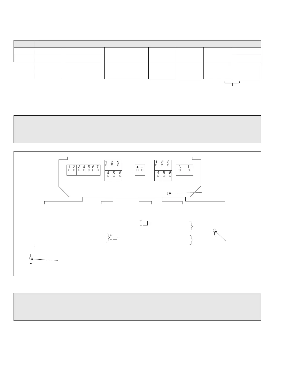
Fig. 4.4 Wall- / Pipe-mount Analyzer Connections
Note.
1. A second retransmission output is available if the RS485 serial communications facility is not used.
2. If
Test Cleaner is set to YES (see page 28), Relay 2 becomes 'Failed Wiper Alarm' relay.
Turbidity Sensor
7998 Series
(see also Table 4.1)
Serial
RS485
Retransmission
Output
Relay 1
Relay 2
Power Supply
– see Warning on page 13
Earth (Ground) Stud
Earth (Ground)
Stud on Case
Earth (Ground)
Stud on Case
1–White
2–Yellow
3–Red
4 – Green
5 – Black
6–
Blue
7–
Braid
Serial
Retrans.
Relay 1
Relay 2
Power
Supply
1–
2–Rx+
3–Rx–
4–Tx+
5–Tx–
6–0V
(Optional)
Retrans.
Output
2
nd
Retrans.
Output
– see Note 1.
Relay 1
Relay 2
– see Note 2.
N– Neutral
L – Line
–Earth
1–NC
2–C
3–NO
4–NC
5–C
6–NO