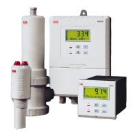
4690 Series
Turbidity systems 6 Operation
IM/4690–EN Rev. A 19
6 Operation
6.1 Analyzer Start-up
Ensure all electrical connections have been made and switch on the power supply. If the system is being commissioned for the first
time, calibration (refer to Section 7, page 20) and parameter programming (refer to Section 8.3, page 27) are required.
6.2 Operation – Turbidity Measurement Mode
Operation in the Turbidity measurement mode comprises an Operating page and a Turbidity Calibration page. The Operating page is a
general use page in which parameters are viewed only and cannot be altered. To alter or program a parameter, refer to the
programming pages in Section 8. The
Turbidity Calibration page enables a calibration to be carried out. A 5-digit calibration code is
used to prevent unauthorized access to the Turbidity Calibration page. The value is preset at 00000 to allow access during
commissioning, but should be changed to a unique value, known only to authorized operators, in the
Set Up Outputs page –
see page 30.
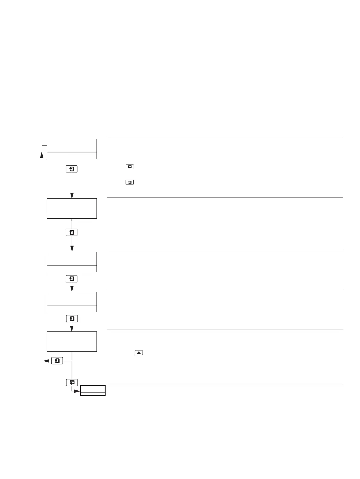
6.2.1 Operating Page
Measured Turbidity (Units)
The measured turbidity value is displayed in the units selected in the
Set Up Parameter page – see
Section 8.3, page 27.
Press to advance to next page
or
Press to advance to next parameter.
Sensor Voltage
The sensor voltage displayed is the output from the optical receiver. The optical system (the emitter
and the receiver) are configured to produce the 0 to 3 V outputs from zero to full scale, providing an
indication of the performance of the optical system.
Alarm 1 Set Point
The set point value and relay / LED action are programmable – refer to Section 8.4, page 29.
Alarm 2 Set Point
The set point value and relay / LED action are programmable – see refer to Section 8.4, page 29.
Manual Clean
Note. Displayed only if the turbidity sensor is fitted with a wiper unit – see Table 2.1, page 3.
Press the key to initiate a manual clean. Manual Clean Yes is displayed for one minute. The
automatic clean sequence is then reset and Manual Clean No displayed.
Advance to
Calibration page – see Section 7, page 20.
Sensor Voltage
3374
.
Alarm 2 Setpoint
500
.
Alarm 1 Setpoint
1500
.
Turbidity (FNU)
4517
.
Manual Clean No
SENSOR CAL.
-----