Operation Manual / A170-M.. - A175-M..
1 Introduction / 1.5 Layout and function of the turbocharger
© Copyright 2022 ABB. All rights reserved. HZTL4033_EN Rev.K January 2022
Mode of operation
The turbocharger is a turbomachine consisting of two main components, a turbine and a
compressor. These components are mounted on a common shaft and form the rotor.
In the turbocharger shown in the illustration, the exhaust gas flows through the gas inlet
casing(06) and the nozzle ring(07) and arrives at the turbine(08). The turbine utilises the
energy contained in the exhaust gas to drive the rotor. The exhaust gases then escape into
the open air through the gas outlet casing(05) and the exhaust gas pipe connected to it.
The rotor runs in two radial plain bearings, which are located between the compressor and
the turbine in the bearing bush(04). The axial bearing is also a plain bearing. The plain bear-
ings are connected to a central lubricating oil duct which is normally supplied by the lubric-
ating oil circuit of the engine. The oil outlet is situated at the lowest point of the bearing
casing(09).
The compressor wheel(02) connected to the shaft draws in fresh air through the filter silen-
cer(01) or the air suction branch. The air is compressed in the compressor and the down-
stream diffuser(03) and then led to the charge air cooler via the compressor casing(10).
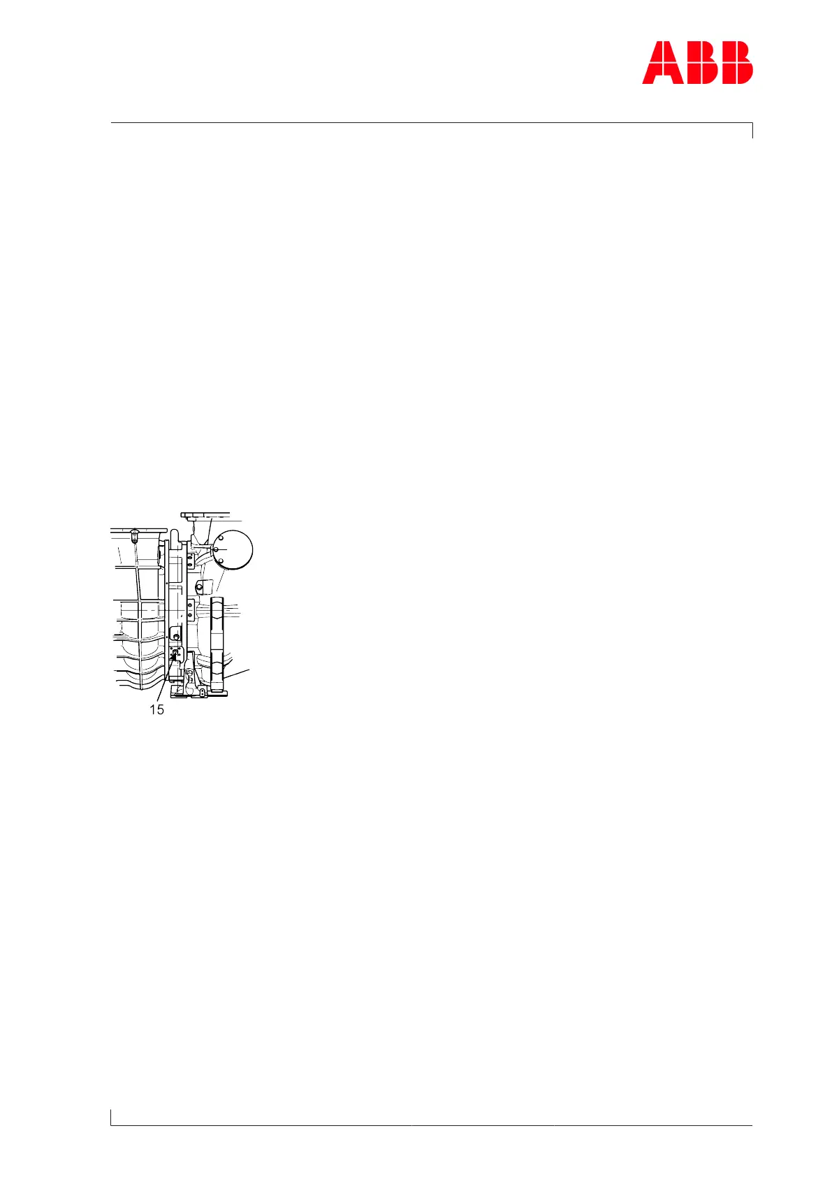
Turbocharger version with compressor wheel cooling
Fig.3: Connection of the compressor wheel cooling
Depending on the application, the turbocharger is equipped with compressor wheel cooling.
With compressor wheel cooling, after the compressor air has cooled down by passing
through the charge air cooler on the engine side, it is supplied to the turbocharger for cool-
ing the compressor wheel.
Cooling of the compressor wheel is compulsory to ensure the reliability and replacement in-
tervals for the relevant operating conditions. In the turbocharger version with compressor
wheel cooling, the cooling air is supplied through the lateral connection (15) in the bearing
casing.
Page 7 / 146
 Loading...