Resistor braking
145
Resistor installation and wiring
All resistors must be installed outside the drive module in a place where they will
cool.
WARNING! The materials near the brake resistor must be non-flammable. The
surface temperature of the resistor is high. Air flowing from the resistor is of
hundreds of degrees Celsius. Protect the resistor against contact.
Use the cable type used for drive input cabling (refer to chapter Technical data) to
ensure the input fuses will also protect the resistor cable. Alternatively, two-
conductor shielded cable with the same cross-sectional area can be used. The
maximum length of the resistor cable(s) is 10 m (33 ft). For the connections, see the
power connection diagram of the drive.
If ordered, the resistors are factory installed in a cubicle(s) next to the drive cabinet.
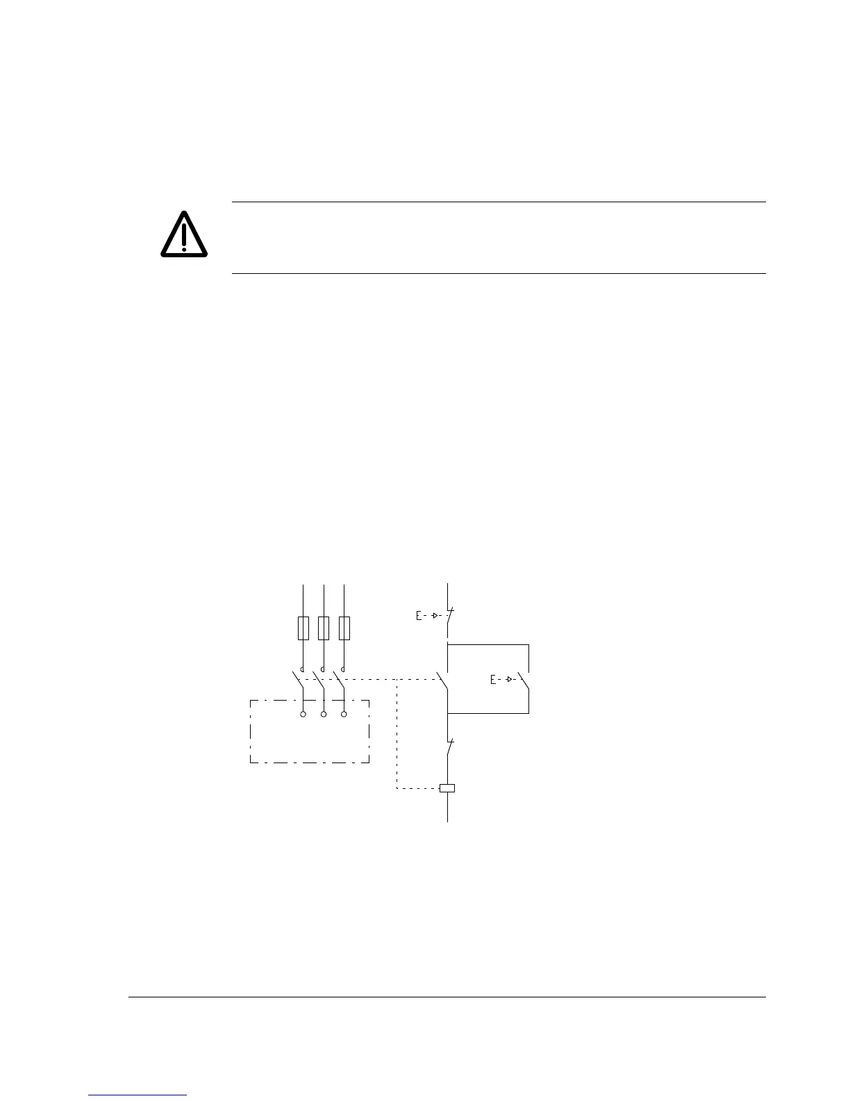
Protection of frame size R5
It is highly recommended to equip the drive with a main contactor for safety reasons.
Wire the contactor so that it opens in case the resistor overheats. This is essential
for safety since the drive will not otherwise be able to interrupt the main supply if the
chopper remains conductive in a fault situation.
Below is a simple example wiring diagram.