Start-up 19
Speed measurement with encoder/resolver
An encoder/resolver feedback can be used for more accurate motor control.
Follow these instructions when encoder/resolver interface module FEN-xx is installed in drive
option Slot 1 or 2. Note: Two encoder interface modules of the same type are not allowed.
Select the used encoder/resolver. For more information,
see parameter group 90 Enc module sel on page 191.
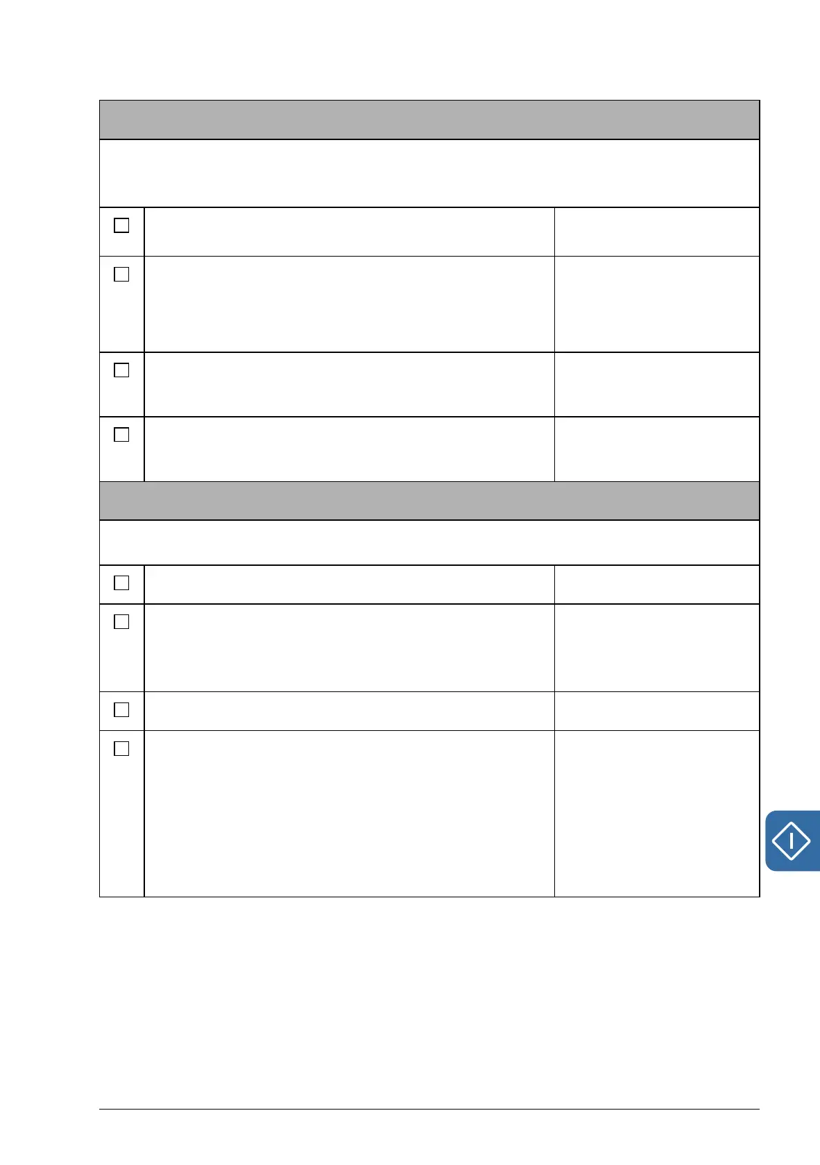
90.01 Encoder 1 sel
90.02 Encoder 2 sel
Set other necessary encoder/resolver parameters:
• Absolute encoder parameters (group 91, page 193)
• Resolver parameters (group 92, page 196)
• Pulse encoder parameters (group 93, page 196).
91.01…91.31
92.01…92.03
93.01…93.13
Save new parameters settings into the permanent
memory by setting parameter 16.07 Param save to value
Save.
16.07 Param save
Set parameter 90.10 Enc par refresh to Configure (or
switch the drive power off and on again) so that the new
parameter settings take effect.
90.10 Enc par refresh
Checking the encoder/resolver connection
Follow these instructions when encoder/resolver interface module FEN-xx is installed in drive
option Slot 1 or 2. Note: Two encoder interface modules of the same type are not allowed.
Set parameter 19.02 Speed fb sel to Estimated. 19.02 Speed fb sel
Enter a small speed reference value (for example 3% of
the nominal motor speed).
Reference can be entered on the control panel by
selecting REF EDIT in the main menu.
Start the motor by pressing the START button.
Check that the estimated (01.14 Motor speed est) and
actual (01.08 Encoder1 speed / 01.10 Encoder2 speed)
speeds are equal. If the values differ, check the encoder/
resolver parameter settings.
Hint: If the actual speed (with a pulse encoder) differs
form the reference value by a factor of 2, check the pulse
number setting (93.01 Enc1 pulse nr / 93.11 Enc2 pulse
nr).
01.14 Motor speed est
01.08 Encoder1 speed
01.10 Encoder2 speed