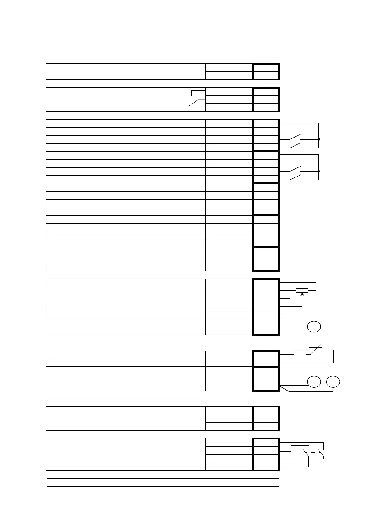
X1
External power input
24 V DC, 1.6 A
+24VI 1
GND 2
X2
Relay output
NO 1
COM 2
NC 3
X3
+24 V DC* +24VD 1
Digital I/O ground DGND 2
Digital input 1: Stop/Start DI1 3
Digital input 2 DI2 4
+24 V DC* +24VD 5
Digital I/O ground DGND 6
Digital input 3: Process or Speed control DI3 7
Digital input 4: Constant speed 1 DI4 8
+24 V DC* +24VD 9
Digital I/O ground DGND 10
Digital input 5 DI5 11
Digital input 6 DI6 12
+24 V DC* +24VD 13
Digital I/O ground DGND 14
Digital input/output 1 DIO1 15
Digital input/output 2 DIO2 16
+24 V DC* +24VD 17
Digital I/O ground DGND 18
Digital input/output 3 DIO3 19
X4
Reference voltage (+) +VREF 1
Reference voltage (–) -VREF 2
Ground AGND 3
Analog input 1: Process or Speed reference
(Current or voltage, selectable by jumper J1)
AI1+ 4
AI1- 5
Analog input 2: Process feedback
(Current or voltage, selectable by jumper J2)
AI2+ 6
AI2- 7
AI1 current/voltage selection J1
AI2 current/voltage selection J2
Thermistor input TH 8
Ground AGND 9
Analog output 1 AO1 (I) 10
Analog output 2 AO2 (U) 11
Ground AGND 12
X5
Drive-to-drive link termination J3
Drive-to-drive link.
B1
A2
BGND 3
X6
Safe Torque Off. Both circuits must be closed for the drive
to start.
OUT1 1
OUT2 2
IN1 3
IN2 4
Control panel connection X7
Memory unit connection X205
T
PT