82 EL3000 CONTINUOUS GAS ANALYZERS | CI/EL3000-EN REV. C
… 4 Installation
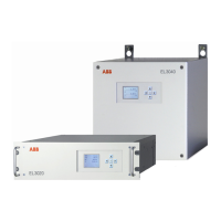
Gas Analyzer Installation
Damage to the device due to unsuited installation site
• The installation site must be sufficiently stable to support
the weight of the gas analyzer (see Housing design on
page 15)
• The 19” housing must be supported in the cabinet or on
the rack with mounting rails!
Injury hazard due to heavy weight
Depending on the version, the gas analyzer weighs7 to 15 kg
(19” housing – model EL3020) or 13 to 21 kg (wall-mounted
housing – model EL3040)!
• Two persons are required for unpacking and
Materials required (not included in the scope of delivery)
19” housing (model EL3020)
• 4 raised head screws (recommendation: M6; this depends on
the cabinet/rack system)
• 1 pair mounting rails (design depending on the cabinet/
frame system), length approx. 240 mm corresponding to
approx. ⅔ of the housing depth
Wall-mount housing (model EL3040)
• 4 screws M8 or M10
Gas Analyzer Installation
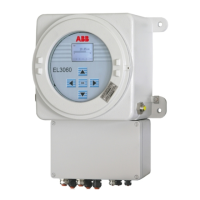
Mount the gas analyzer in the cabinet / rack or on the wall.
Observe the dimension diagram (see Dimensions on page 35).
Mount several 19” housings with a minimum distance of 1 HE
between each housing,
Special conditions for the Fidas24 gas analyzer
If the gas analyzer is installed in a closed cabinet, adequate
ventilation of the cabinet must be provided (at least 1 change of
air per hour).
Special conditions for the model EL3020 gas analyzer for
the measurement of flammable gases
Unrestricted exchange of air with the environment must be
provided around the gas analyzer from the bottom (floor plate)
and from the rear (gas connections).
The gas analyzer may not be placed directly on a table.
The housing openings may not be closed. Spacing to adjacent
built-in components to the sides must be at least 3 cm.
If the gas analyzer is installed in a closed cabinet, adequate
ventilation of the cabinet must be provided (at least 1 change of
air per hour).
The spacing to adjoining fittings from the bottom (floor plate)
and from the back (gas connections) must be at least 3 cm.
Special conditions for the model EL3040 gas analyzer in
degree of protection II 3G
Protection against mechanical influences
Due to the low mechanical stability of the viewing glass, the gas
analyzer must be designed and operated in such a way that
mechanical damage to the viewing glass is excluded with an
energy greater than 2 J.
UV radiation protection
Due to the low UV resistance of the plastic parts of the housing,
the gas analyzer must be designed and operated in such a way
that the effect of UV radiation can be excluded.
 Loading...
