84 EL3000 CONTINUOUS GAS ANALYZERS | CI/EL3000-EN REV. C
… 4 Installation
Fidas24 – Connect gas lines
Safety instructions
Explosion hazard
Explosion hazard due to leaking combustion gas in the gas
analyzer.
• The leak tightness of the combustion gas supply line
outside the gas analyzer as well as the combustion gas
path in the gas analyzer must be checked regularly.
• The relevant safety regulations for working with combustion
gases must be complied with!
• The screwed connections of the gas paths in the gas analyzer
may not be opened! The gas paths can become leaky as a
result.
– However, if the screwed connections of the gas paths in
the gas analyzer have been opened (only by trained
personnel), a leak tightness test must be performed
using a hydrogen detector (for example, based on
thermal conductivity) must always be carried out after
they have been sealed again. The leakage rate must not
exceed 10
-4
hPa⋅l/s.
• The lines and fittings must be clean and free of any residues
(for example, particles left from manufacturing)!
– Contaminants can enter the analyzer and damage it or
lead to false measurement results!
Notes
• The installation of gas connections is described in Mounting
the fittings on the gas analyzer on page 41.
• Follow the manufacturer's installation instructions for the
fittings! In particular, hold the male fittings (gas
connections) in place when connecting the gas lines.
• When laying and connecting the gas lines, adhere to the
installation instructions provided by the manufacturers of
the piping!
• If gas lines made of stainless steel are connected to the
analyzer modules, the lines must be connected to the
building-side potential equalization.
• Never connect more than three analyzer modules in a series!
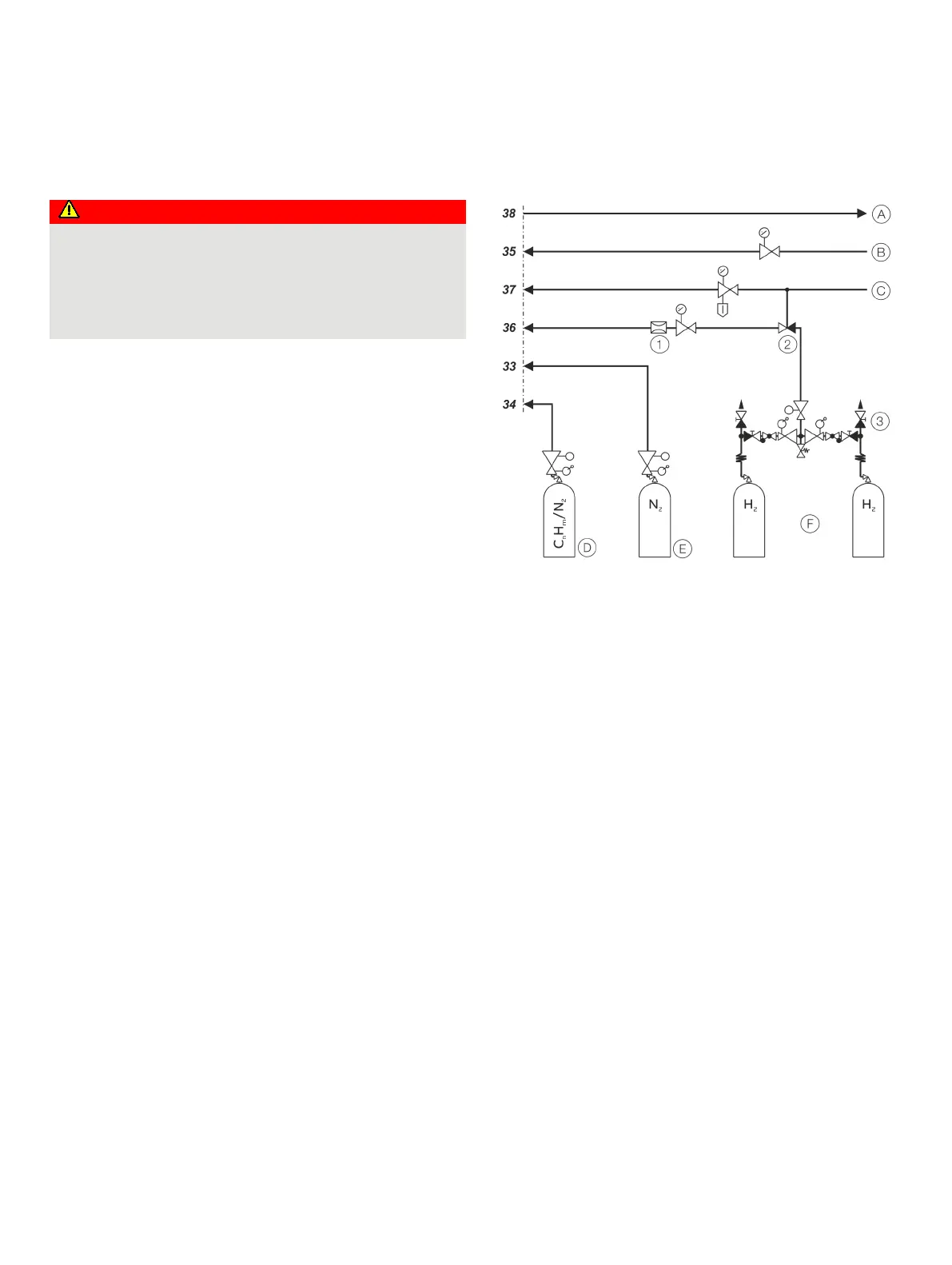
Connection of process gases and test gases
Flow restrictor
Pneumatic shutoff valve
Switching station with safety
valve
Exhaust air
Combustion air
pe = 1200 hPa, ±100 hPa
Instrument air
pe = 4000 hPa, ±500 hPa
Span gas
pe = 1000 hPa, ±100 hPa
Zero point gas
p
e
= 1000 hPa, ±100 hPa
Switching station with safety
valve
combustion gas pe = 1200 hPa,
±100 hPa
Figure 34: Connection of process gases and test gases
The numbering of the gas connections corresponds to the
numbering in Figure 32 and Figure 33 as well as the labeling on
the rear of the gas analyzer.
Instrument Air Connection
The instrument air is used as propulsion air for the air jet
injector, and as purging air for the housing purging, see Housing
purge on page 33.
Connect the instrument air line to the instrument air inlet 37 of
the gas analyzer via a pressure regulator (0 to 6 bar).
Combustion air connection
Connect. the combustion air line to the combustion air inlet 35
of the gas analyzer via a pressure regulator (0 to 1.6 bar).
Combustion gas connection
See section Combustion gas connection on page 84.
 Loading...


