98 EL3000 CONTINUOUS GAS ANALYZERS | CI/EL3000-EN REV. C
… 5 Electrical connections
… Connecting the power supply
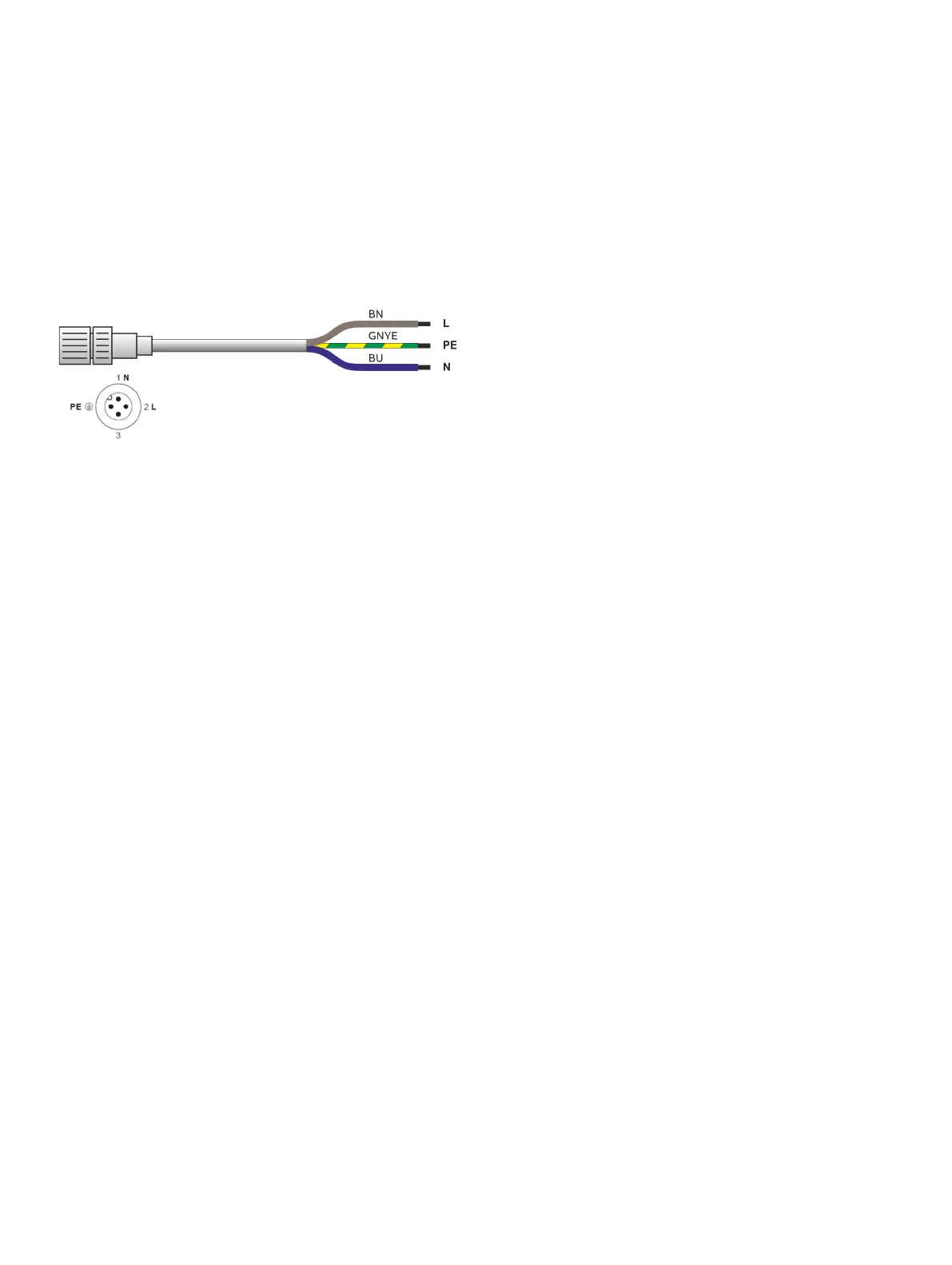
Grid connection cable Fidas24
A connection cable is provided for the power supply
(115 / 230 V AC) for heating the detector and, if necessary, the
heated sample gas connection (length 5 m, cable cross-section
3 × 1.5 mm
2
) with a 4-pole socket connector for the connection
to the analyzer module.
Figure 47: Pin side of the plug 30
The illustration shows the pin side of the plug 30 on the analyzer
(see Figure 32 on page 80).
The operating voltage of the detector heating is automatically
detected and switched. The set voltage can be identified
through two LEDs on the mains distribution card.
Connect power supply lines
1. Ensure that the power supply feeder has an adequately
dimensioned protective device (circuit-breaker).
2. Install an easily accessible mains isolator or a switched
socket in the power supply line, close to the gas analyzer, so
that all the poles of the gas analyzer can be disconnected
from the power supply if necessary. Label the supply circuit
isolator to make it clear that it is associated with the device
that needs to be isolated.
3. Plug the cold device power cable into the power supply
connection X01 (see Figure 38 on page 90 and Figure 39 on
page 91) of the gas analyzer and fasten the plug with the
bracket.
4. Attach the Fidas24 power cable to the power supply
connection 30 (see Figure 32 on page 80 and Figure 33 on
page 81) of the Fidas24 analyzer module and tighten.
5. Connect the other ends of the power cable to the power
supply.
6. If stipulated by the relevant installation regulations, connect
the gas analyzer to the building’s equipotential grounding
system.
Note
The supply circuit isolator must mutually isolate the power
supply of the gas analyzer and the Fidas24.
Note
The gas analyzer can be put into operation as soon as it is
connected to the power supply of the building.
 Loading...


