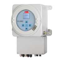
EL3060 CONTINUOUS GAS ANALYZERS | OI/EL3060-EN REV. A 41
Analog outputs
0/4 to 20 mA (pre-set ex works to 4 to 20 mA, see page 95), common nega-
tive pole, electrically isolated to ground, can be connected to ground as re-
quired, in this regard, max. gain compared to local protective ground poten-
tial 50 V, working resistance max. 750 Ω. Resolution 16 bit. The output signal
may not be less than 0 mA.
An analog output is allocated in the sequence of the sample components for
each sample component. The sequence of the sample components is docu-
mented in the analyzer data sheet (see page 33) and on the type plate (see
page 33).
NOTE
The assignment of the terminals (see page 95) can be changed in the con-
figurator.
Modbus, Profibus
As an option, either the Modbus module or the Profibus module can be in-
stalled in the gas analyzer.
Ethernet port
The Ethernet 10/100BASE-T interface of the gas analyzer is used
• for communication with the ECT configuration software (see page 53)
for gas analyzer configuration and software update
• for data transmission using the Modbus TCP/IP protocol and
• for transmission of the QAL3 data, if the option QAL3 monitoring (see
page 107) has been integrated in the gas analyzer.
Analyzer unit EL3060-Uras26
• Data transfer: terminals 21 to 29 (SPI1 to SPI9) for lines 1 to 9 (inscription
on the lines)
• Power supply: terminals 34 (GND) and 68 (+24V, line with red marking),
separate PE connection
Power supply
• Terminals L, N, PE
Design of the electrical connections
• Terminal blocks with screw connection
• Conductor size:
• single-core: 0.5 to 4 mm
2
• multi-core: 1.5 to 4 mm
2
• stranded: 0.5 to 2.5 mm
2
(only with wire end ferrule)