EasyManua.ls Logo

ABB Endura AZ series User Manual

ABB Endura AZ series
102 pages
To Next Page IconTo Next Page
Page #1 background imageLoading...
Page #1 background image
ABB MEASUREMENT & ANALYTICS | USER GUIDE | IM/AZ20E-EN REV. F
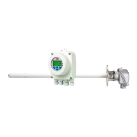
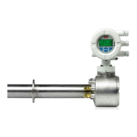
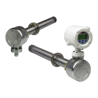
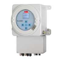
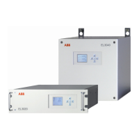
Endura AZ series integral and remote transmitter
Combustion oxygen monitor
Measurement made easy
Superior technology
and quality
from the world
leader in oxygen
measurement
Introduction
The Endura AZ20 is the latest in a long
line of high-quality, combustion gas
analyzers from ABB.
The sensor, based on a zirconium oxide
cell, is mounted at the tip of the probe
that is inserted in the flue duct. The
resulting direct, in situ measurement
provides accurate and rapid oxygen
reading for combustion control
optimization and emissions monitoring.
For more information
Further publications for the Endura AZ series
analyzers are available for free download from:
www.abb.com/measurement
or by scanning this code:
Search for or click on
Data sheet
Endura AZ20 oxygen monitor
Combustion gas analysis
DS/AZ20-EN
Data sheet
Endura AZ25 oxygen analyzer
Combustion gas analysis
DS/AZ25-EN
Maintenance guide
Endura AZ20 series probe
Combustion oxygen monitor
IM/AZ20M-EN
User guide
Endura AZ20 series probe
Combustion oxygen monitor
IM/AZ20P-EN
User guide
Endura AZ25 series probe
Combustion oxygen monitor
OI/AZ25P-EN
This User Guide is intended for use on the
following analyzer systems:
Endura AZ10
Endura AZ20
Endura AZ25

Table of Contents

Questions and Answers:

ABB Endura AZ series Specifications

General IconGeneral
BrandABB
ModelEndura AZ series
CategoryMeasuring Instruments
LanguageEnglish

Summary

Safety

Health & Safety

Guidelines for safe operation and handling of equipment.

Electrical Safety

Compliance with electrical safety standards and requirements.

Safety Precautions

General precautions to avoid injury or equipment damage during operation.

Safety Conventions

Definitions of warning and caution symbols used in the manual.

Safety Recommendations

Key recommendations for safe operation and maintenance procedures.

Mechanical Installation

Unpacking

Instructions for unpacking the transmitter and its components.

Cleaning

Guidelines for cleaning the transmitter, ensuring IP rating.

Installation Conditions – Transmitter

Specifies environmental and location requirements for transmitter installation.

Overall Dimensions

Provides physical dimensions of the remote transmitter.

Electrical Installation

Electrical Safety

Critical safety information regarding electrical installation and grounding.

Remote Transmitter – Access to Terminals

Steps for accessing the internal terminals of the remote transmitter.

Remote Transmitter – Remote AZ10 Sensor Cable Connections

Wiring details for connecting the AZ10 sensor to the remote transmitter.

Remote Transmitter – Power Supply and Output Connections

How to connect power supply and output signals to the remote transmitter.

Integral Transmitter – Probe Cable Connections

Wiring details for connecting the probe to the integral transmitter.

Integral Transmitter – Power Supply and Output Connections

How to connect power supply and output signals to the integral transmitter.

Programming

Navigating Menus and Parameters

How to navigate menus and parameters using the device keys.

Overview of Operator Pages and Menus

Explanation of operator pages, menus, and icons.

Passwords and Security Options

Setting up passwords for different access levels.

Easy Setup

Quick configuration of basic transmitter settings.

Calibrate

Procedures for sensor calibration and test gas setup.

Diagnostics

Viewing diagnostic messages and historical data.

Display

Settings for display mode, autoscroll, and screen contrast.

Communication

Configuring HART communication and data output.

Calibration

Overview of Calibration Procedures

Summary of available calibration types and their descriptions.

Calibrating the System

Step-by-step guide for performing system calibration routines.

HART®-Protocol

Hardware and Software Requirements

Lists necessary hardware and software for HART communication.

HART-Protocol Connection

Details on how to connect the transmitter for HART communication.

Device Status Information

Information on device status bytes and error codes.

Troubleshooting

Diagnostics Classification Codes

Explains diagnostic message icons and codes conforming to NAMUR NE107.

Failure Messages

Details failure messages, possible causes, and corrective actions.

Out of Specification Messages

Lists messages indicating parameters outside specifications and solutions.

Maintenance Messages

Lists maintenance-related messages and required actions.

Log Entries

Details on how Performance Log entries are displayed and their icons.

Remote Computer Connection

Utility Software for PC

Overview of ABB Utility Software for PC communication.

Connecting the IrDA Port

Instructions for connecting the transmitter via the IrDA port.

Remote HMI (Human Machine Interface)

Running the Remote HMI application for device control.

Spares and Accessories

Documentation & Software

List of available documentation and software for the product.

Transmitter Spares

Part numbers and descriptions for replacement transmitter components.

System Specification

Measurement Performance

Specifications for measurement accuracy, range, and response time.

Environmental Data

Operating and storage conditions, humidity, and sunlight requirements.

Power Supply

Specifications for the AC power supply and power consumption.

Transmitter Specification

Transmitter enclosures

Types of transmitter enclosures and mounting options.

Automatic calibration

Details on AutoCal hardware and its functionality.

Analog outputs

Specifications for standard and optional analog current outputs.

Digital inputs/outputs

Details on digital I/O capabilities and functions.

Infrared service port

Specifications for the IrDA port and its functions.

Calibration

Manual and automatic calibration types and control methods.

Related product manuals