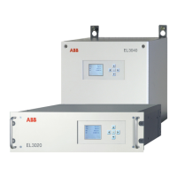
Combustion Oxygen Monitor
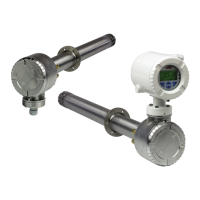
Endura AZ20 Series Probe 5 Dismantling and Reassembly – Probe
16 IM/AZ20M–EN Rev. B
5.7 Replacing the Diffuser Flame Arrestor and / or Cell
Before replacing the cell:
1. Ensure a replacement cell kit is available – refer to Section
7.1, page 43.
2. Remove the probe from its mounting as detailed in
Section 5.4, page 14 (integral probe) or Section 5.5, page
14 (remote probe).
3. Record the cell data printed on the existing cell label –
refer to the probe User Guide (IM/AZ20P–EN) for label
details.
4. Remove the probe end cap as detailed in Section 5.6.1,
page 15.
5.7.1 Removing the Diffuser Flame Arrestor
Referring to Fig. 5.4:
1. At the probe head, disconnect the red (Cell +), green (TC+)
and white (TC–) wires
A from the inner terminal block
connections and straighten the wires.
2. Unscrew and remove M4 screw
C to release the spring
loading on the thermocouple / electrode assembly.
3. At the probe cell end, loosen the 6 M4 x 50 bolts D using
an M4 spanner and 3 mm A/F hexagon wrench (supplied).
If the bolts are seized, use a small hacksaw to cut the
through the bolts at the recess between the diffuser flame
arrestor and the probe end plate
E.
4. Remove the 6 M4 x 50 bolts.
5. Carefully withdraw the diffuser flame arrestor
F while
supporting the cell G. If necessary, use a solvent, for
example lighter fluid (petroleum ether) or alcohol (surgical
spirits) to lubricate the joint between the diffuser flame
arrestor and probe end.
6. Proceed to Section 5.7.2, to fit a new cell.
5.7.2 Removing the Cell and C-ring
Referring to Fig. 5.4:
1. Remove the test gas injection pipe H from the cell
housing and retain for re-assembly.
2. Carefully attempt to withdraw the cell I from the cell
housing using minimal force.
– If the cell can be withdrawn freely, proceed to step
4.
– If the cell does not move (is stuck in the probe
body), use a spanner on the 2 flats to rock it
sideways gently until loose – do not rotate more than
2 to 3 mm (0.08 to 0.12 in.)
. If this action frees the cell
proceed to step 4.
– If the cell cannot be withdrawn freely and is welded
to the thermocouple / electrode contact assembly,
proceed to step 3.
3. If the cell is welded to the helical contact at the end of the
thermocouple / electrode assembly, carefully withdraw the
cell and thermocouple / electrode contact assembly until
the cell tip
J is visible.
Use a sharp blade to cut between the wire nest and cell
tip and separate the 2 items K. Take extreme care not to
damage either item.
4. Remove and discard 'C-ring
L.
If the C-ring is stuck, insert a small screwdriver blade in
the hollow of the C-ring M and gently prise it in several
places until free.
5. Proceed to Section 5.7.3, page 18 to fit a new cell.
Warning. When in operation, the cell end of the probe
reaches temperatures up to 100 °C (212 °F). Allow the cell
to reach ambient temperature before starting maintenance
procedures.
Note. Check all items for damage as they are removed. Do
not re-use the nuts or bolts, always replace damaged items
with new parts.
Note. It is recommended that a replacement
thermocouple / electrode assembly (refer to Section
7.7, page 44) is also available in case the existing
assembly is damaged during cell replacement.
Note. AutoCal versions only – if necessary,
disconnect the test gas to sensor tube to enable
access to the green (TC+), white (TC–) and red (Cell+)
terminals.
Caution. Do not use oil or release agents – these will
damage the components.
Caution. Do not touch the sealing face or ID of the
probe recess with the screwdriver blade. The surface
finish must be undamaged to maintain the C-ring’s
sealing properties.
 Loading...
