Combustion Oxygen Monitor
Endura AZ20 Series Probe 5 Dismantling and Reassembly – Probe
IM/AZ20M–EN Rev. B 27
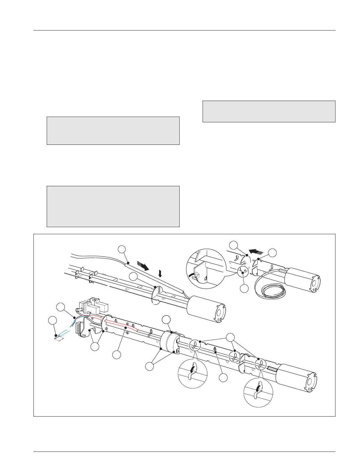
5.9.3 Assembling the New Heater Assembly
Referring to Fig. 5.12:
1. Join the heater assembly end plate
A and the inner
assembly support column end plate B and secure the
end plates to each other by carefully folding the 4 heater
assembly end plate tabs
C down.
2. Slide the first insulator D over the heater wires and
position it in the slot E.
3. Fold the insulator retaining tabs F down to secure the
first insulator to the extension support column.
4. For 1.0 m (3.28 ft.) probes and longer, slide the remaining
insulators along the heater wires. Ensure wires are not
crossed in the insulator channels and position the
insulators between the slots in each column. Ensure each
insulator butts up to the previous insulator.
Secure each insulator by folding alternate insulator
retaining tabs down on each section of the inner support
assembly.
5. Refit the 2 parts of the thermal barrier sections
H and
secure them using the length of wire
I (supplied). Wind
2 turns and twist the ends together.
6. Pass the 2 heater wires
J through the openings in the
internal structure mounting plate / end plate
K.
7. Slide the red sleeve
L over the heater wires until it butts
up to the last insulator.
8. Prepare the heater wires M for re-connection by cutting
back approximately 4 mm (0.2 in.) of heatshrink sleeve
from each wire. Do not cut the heater wires
9. Proceed to Section 5.9.4, page 28 to refit the inner
assembly.
Note. If tabs break, use the spare unused tabs G.
Avoid folding tabs within 20 mm (0.8 in.) of insulator
joints.
Note. To prevent the oven leads from shorting to the
metalwork of the inner column(s) at elevated process
temperatures, all insulator joints should be spaced
100 mm (4 in.) or more from the slots
E in each inner
assembly support column.
Caution. DO NOT use tape, this section operates at
temperatures up to 400 °C (750 °F).
Fig. 5.12 Assembling the New Heater Assembly – 0.5 m (1.64 ft.) probe shown

 Loading...


