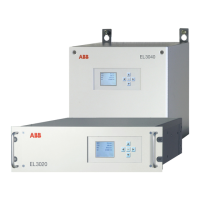
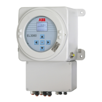
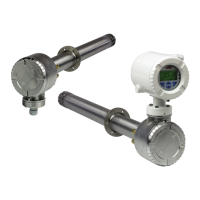
Combustion Oxygen Monitor
Endura AZ20 Series Probe 5 Dismantling and Reassembly – Probe
IM/AZ20M–EN Rev. B 31
5.10.2 Fitting an AutoCal Assembly
Referring to Fig. 5.16:
1. Locate the AutoCal manifold
A on the internal mounting
plate with the pressure switches (PS1 and PS2) at the
front of the plate (the same side as the 9-way terminal
block). Secure the manifold using the 2 M3 screws
B
(supplied).
2. On remote probes, locate the 6-way AutoCal terminal
block / plug C and secure it using the 2 M3 screws D
(supplied). On integral probes, the terminal block is already
fitted and the terminal plug cable connections are already
made.
3. If not already fitted, push the Pressure Switch loom
connections onto the Pressure Switch terminals
E as
follows:
– White / Orange (PS1)
– White / Black (PS COM)
– White / Yellow (PS2)
– White / Black (PS2 COM to PS1 COM terminal)
4. If not already fitted, push the Solenoid Valve loom
connections onto the Solenoid Valve terminals
F as
follows:
– White / Red (SV2 COM to SV1 COM terminal)
– White / Blue (SV2)
– White / Red (SV1 COM)
– White / Green (SV1)
5. Make Pressure Switch loom connections to the (inner)
terminal block terminals
G.
6. Feed the Solenoid Valve loom wires under the internal
structure mounting plate and make Solenoid Valve loom
connections to the (inner) terminal block terminals H.
Route the wires clear of the thermocouple / electrode
assembly insulators and away from the mounting plate
fixing points to ensure the do not become trapped.
7. If the cell was removed for checking / replacement in
Section 5.7.2 page 16, ensure it is fitted before
proceeding – refer to Section 5.7.3, page 18.
Note. Refer to Appendix B.4, page 50 for AutoCal manifold
block orientation details.
Fig. 5.16 Fitting the AutoCal Manifold and
Making Terminal Block Connections
White /
Orange
White / Black
(PS1 COM)
White / Yellow
(PS2)
White / Black
(PS2 COM)
White / Red
(SV2 COM)
White / Blue
(SV2)
White / Red
(SV1 COM)
White / Green
(SV1)
Pressure Switches
Solenoid Valves
 Loading...
