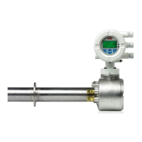
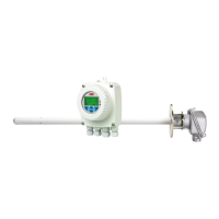
Combustion Oxygen Monitor
Endura AZ20 Series Probe 5 Dismantling and Reassembly – Probe
20 IM/AZ20M–EN Rev. B
5.8 Replacing the Thermocouple /
Electrode Assembly
Before replacing the thermocouple and electrode assembly:
1. Ensure replacement thermocouple and electrode
assembly and C-ring kits are available – refer to Section
7.7, page 44.
2. Remove the probe from its mounting – refer to Section
5.4, page 14 (integral probe) or Section 5.5, page 14
(remote probe).
3. Remove the probe end cap as detailed in Section 5.6.1,
page 15.
5.8.1 Removing the Thermocouple / Electrode Assembly
Referring to Fig. 5.7:
1. At the probe head, disconnect the red (Cell +), green (TC+)
and white (TC–) sleeved wires
A from the inner terminal
block connections.
2. Unscrew and remove M4 screw
C.
3. Check if the cell is welded to the electrode tip by gently
pulling the white and green sleeved wires D.
4. If resistance is felt, check if cell is welded to the helical
contact at the end of the thermocouple / electrode
assembly – refer to Section 5.7.2, page 16 (step 3). When
the cell has been released / removed, proceed to step 5.
5. The thermocouple / electrode assembly is very fragile, so
withdraw the thermocouple / electrode assembly F from
the probe body carefully, providing support G along the
length of the assembly and keeping it straight.
6. Lay the thermocouple / electrode assembly on a long
clean flat surface.
7. Proceed to Section 5.8.2, page 22 to fit a new
thermocouple / electrode assembly.
Note. Check all items including the extension insulators for
damage as they are removed. Keep items for reuse in a
clean safe place. Replace any damaged items with new
replacements. Never reuse damaged insulators.
Caution. AutoCal versions only – if necessary,
disconnect the test gas to sensor tube B to allow
access to the terminal connectors.
Caution. Do not pull the Cell + (red sleeve) wire E
to check for thermocouple / electrode assembly play.
 Loading...
