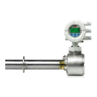
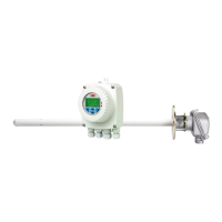
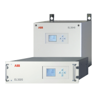
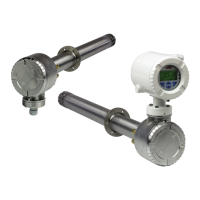
Combustion Oxygen Monitor
Endura AZ20 Series Probe 5 Dismantling and Reassembly – Probe
24 IM/AZ20M–EN Rev. B
5.9 Replacing the Heater Assembly
Before replacing the heater assembly:
1. Ensure replacement heater and C-ring kits are available –
refer to Section 7.6, page 44.
2. Remove the probe from its mounting as detailed in
Section 5.4, page 14 (integral probe) or Section 5.5, page
14 (remote probe).
3. Remove the probe end cap as detailed in Section 5.6.1,
page 15.
4. Remove the thermocouple / electrode assembly as
detailed in Section 5.8.1, page 20.
5.9.1 Removing the Heater Assembly
Referring to Fig. 5.10:
1. Disconnect the internal earth connection
A.
2. If AutoCal is fitted, disconnect Test Gas 1 and 2 tubes B
from the AutoCal manifold by pressing blue release ring
C in and pulling the tube out.
3. AZ20 Probes only – disconnect the internal Reference Air
tube D from the connection on the probe body.
AZ20/ZFG2 Replacement Probes only – disconnect the
internal Reference Air tube E (connected to the internal
conduit) from the connection on the probe body.
4. Disconnect the Test Gas to Sensor tube F at the centre
connection.
5. Disconnect heater wires G from the terminal block (blue)
and (brown) connections.
6. If transmitter wires are present, unscrew the terminal plug
retaining screws
H from terminal block(s) I and
remove terminal plug(s) J from the socket(s).
7. Remove the 3 internal structure mounting plate M4
screws K using the 3 mm A/F hexagon wrench
(supplied).
8. Carefully withdraw the inner assembly L, supporting it
along its length as it is withdrawn and place it on a flat
clean surface.
9. Proceed to Section 5.9.2, page 26 to dismantle the
existing heater assembly.
Note. Check all items for damage as they are removed.
Keep items for reuse in a clean safe place. Replace all
insulators with the new ones supplied in the kit. Do not
reuse damaged insulators.
Note. Do not remove the heater assembly until the
thermocouple / electrode assembly has been
removed.
Note. If resistance is felt, press and hold the blue
release ring and push the tube into the connector then
withdraw it. Do not damage the Test Gas 1 and 2
tubes – damaged tubes may not seal when
re-connected and could result in permanent damage
to the fitting.
Note. If resistance is felt, rotate the probe body
through 45 ° to 90 ° to free the inner assembly.
 Loading...
