CO₂ AND HUMIDITY
CO₂
CONTROL
A CO₂ sensor should be wired to UI4, and UI4Config (A174) is set to 0.
This will take a voltage signal from 0-10V.
To adjust the CO₂ reading dependent on altitude above sea level, enter the height in ft into the altitude
(A215) analog setpoint.
• On a rise in zone CO₂ levels above the CO2_Stpt (A223), the VAV box flow will reset upwards to the
maximum flow setpoint.
• To disable the CO₂ flow reset based on CO2, set enableCO2_DCV (D270) to FALSE. This may be
necessary on cooling only boxes with no supplemental heat.
The minimum CO₂ range in ppm is set using minCO2Range (A278), and the maximum CO₂ range is set
using maxCO2Range (A280) analog setpoint.
HUMIDITY MONITORING
Humidity will be monitored by the CBT-Stat or if UI4Config (A174) is set to 1 and a 0-10v humidity
sensor is wired.
WINDOW SENSOR AND FAN STATUS
WINDOW SENSOR
If an input has been configured for a window sensor, the input is N.O. when the window state is closed.
When a window has been opened, the input will close. The status is read at windowOpen (D251).
When a window has been detected open:
• Heating and cooling are disabled.
• Damper is closed.
• Any VAV fans are disabled.
FAN STATUS
If UI 4 has been configured for fan status, the input is N.O. when the fan is off. When the fan is energized,
the input will close. The fanConfig (A54) analog setpoint should be set for either parallel or series fan
control. The status is read at fanStatus (D88).
• If the series or parallel fan has been commanded ON and no fan status has been detected within 30
seconds, a fan alarm will be generated.
DAMPER CONTROL
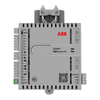
The FBVI-2U4-4T controller provides pressure-independent zone temperature control by calculating
airflow rate setpoints based on the space temperature deviation from zone setpoint and the duration of
deviation. The primary inlet airflow rate is measured and compared to this control point. Any error
greater than the deadband setting will cause the primary air damper to be driven open or closed as
required to reduce the error to within an adjustable Flowrate deadband.
The primary airflow setpoint is read from point activeFlowSetpoint (A236).
Specific details on airflow and airflow setpoints can be reviewed in Section 3 Control sequences.

 Loading...