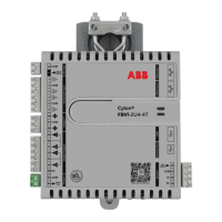
FBVi-2U4-4T | APPENDIX: List of
©ABB 2021 All Rights Reserved.
Subject to change without notice
WWW.CYLON.COM
Output hardware setup for first stage of Heat
1 = 0-10V
2 = 2-10V
3 = Float
4 = Custom for AO14
Output hardware setup for second stage of Heat
1 = 0-10V
2 = 2-10V
4 = Custom for AO15
After zeroing airflow, calculated offset.
Configuration for the heat staging. Calculated with
the CXPro Bacnet commission tool. Add values
together for the total.
0 = no heat
1 = one stage heat
2 = two stages heat
4 = three stages heat
16 = perimeter heat primary
32 = duct hand perimeter simultaneous operation
64 = dual max control on
The current terminal load. -100 to +100%
Calculated discharge air temperature setpoint.
Minimum is 50°F (10°C)
If duct temperature is above setpoint, heat will be
locked out until it falls below 120°F (49°C).
Configuration for fan control.
0 = No Fan
1 = On/Off Series Fan
2 = On/Off Parallel Fan
4 = Variable Series Fan
8 = Variable Parallel Fan
If the unit is configured for heat control with
heatConfig
, set the number of stages for perimeter
heat. Perimeter heat will directly control zone
temperature. Set 0-3 stages.
Used for network assignment of the occCmd . Used
when utilizing Tx modules. Not for BACnet use.
Used for network assignment of the HVACMode.
Used when utilizing Tx modules. Not for BACnet use.
Set the occupied Cooling Setpoint.
Set the occupied Heating Setpoint
Set the unoccupied Cooling Setpoint
Set the unoccupied Heating Setpoint
When a potentiometer is used on UI2 for setpoint
offset, the maximum Ohm range of the span.
The allowable temperature range for the
potentiometer is used on UI2 . 4 = +2 deg and -2 deg
from setpoint.
Box size of the VAV. Sets an initial KFactor before
balancing. Once the box is balanced, this value is
replaced.
1 = 4"Box
2 = 5"Box
3 = 6"Box
4 = 8"Box
5 = 10"Box
6 = 12"Box
7 = 14"Box
8 = 16"Box
When the unit is in Standby Mode, the occupied
heating and cooling setpoints will be offset by this
amount.
Occupied cool stpt + offset
Occupied heat stpt - offset

 Loading...