NoteAction
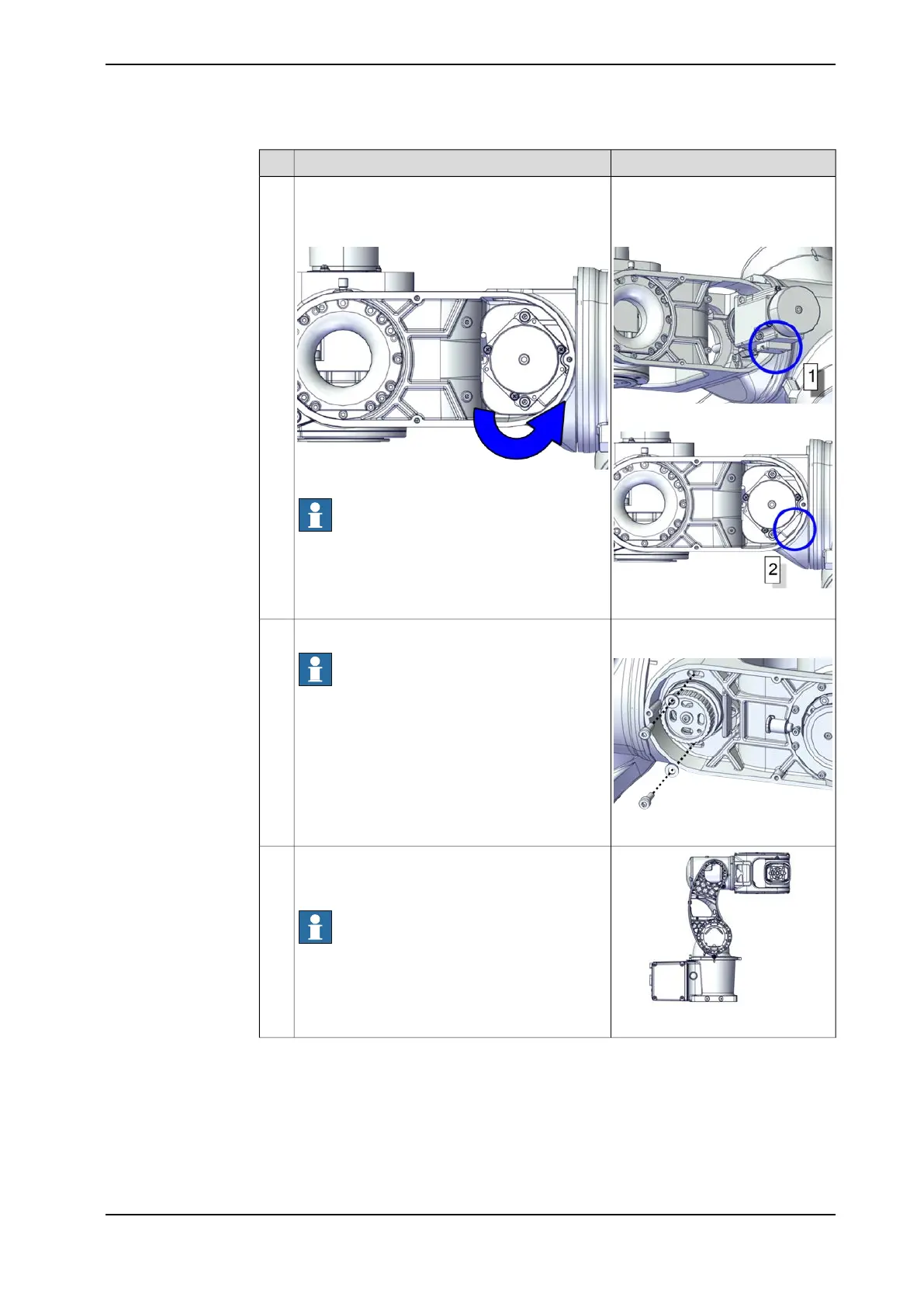
Motor orientation: orient the motor
according to the figures below, in
regard to the encircled motor con-
nector.
Orient the motor into the wrist unit in a leveled
position first (connector reference 1), and then
rotate it 45° when it is in the wrist unit (connector
reference 2).
4
xx2200000104
xx2200000103
xx2200000105
Note
Carefully handle the connectors. Leave the MP5
connector visible and accessible from the process
hub.
Screw: M4x12 12.9 Lafre
2C2B/FC6.9 (2 pcs)
Refit the screws and washers.
Note
Do not tighten the screws yet.
5
xx2200000044
xx2200000120
Connect the power supply to axis-4 motor and
release the axis-4 brake to move the axis 4 to -
90°. Then, disconnect the power supply.
Note
The robot is not connected to the controller during
replacement, power must be supplied to the con-
nector R1.MP according to the section Supplying
power to connector R1.MP on page 56.
6
Continues on next page
Product manual - IRB 1010 219
3HAC081964-001 Revision: B
© Copyright 2022 ABB. All rights reserved.
5 Repair
5.4.3 Replacing the axis 3-4 assembly unit
Continued