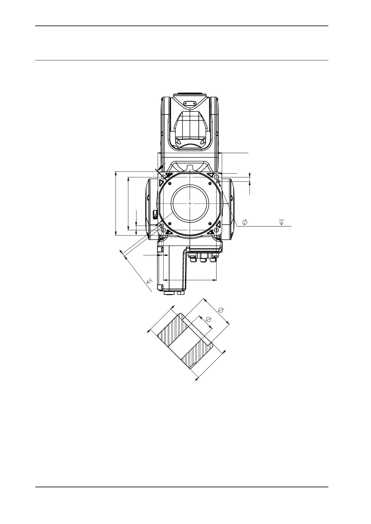
Hole configuration, base
This illustration shows the hole configuration used when securing the robot.
7
110
110
2
6 H7
+
0,012
0
8
6 H8
+
0,018
0
8
135
9
9
4
4
132
J
J
4x14,3
4x
9
4x
18
4x16,7
SECTION J-J
xx2200000191
54 Product manual - IRB 1010
3HAC081964-001 Revision: B
© Copyright 2022 ABB. All rights reserved.
3 Installation and commissioning
3.3.2 Orienting and securing the robot
Continued