2 Installation and commissioning
2.4.4. Installation of additional mechanical stops on axis 3
753HAC026660-001 Revision: C
© Copyright 2006-2008 ABB. All rights reserved.
Required equipment
Installation of mechanical stop, axis 3
The procedure below details how to install the mechanical stop to axis 3.
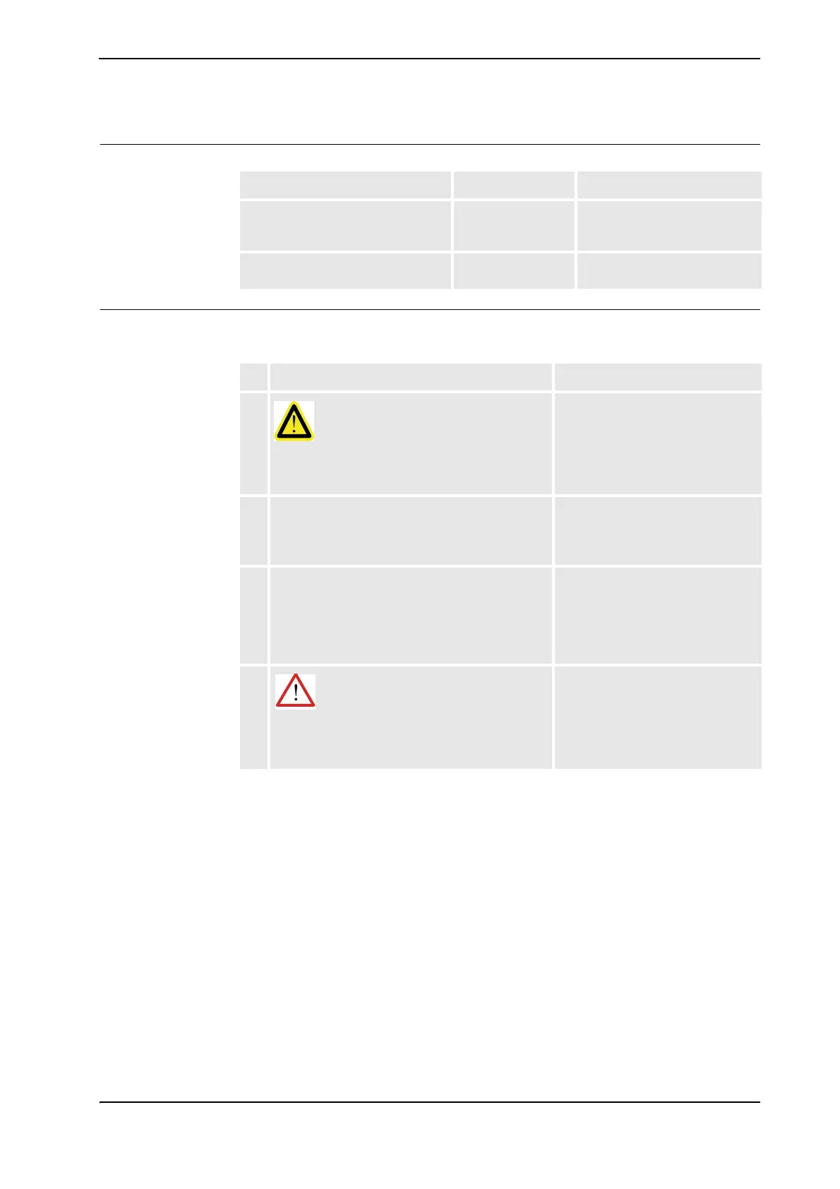
Equipment Art. no. Note
Working range limit axis 3 3HAC023109-001 Includes mechanical stop,
attachment screws and
washers.
Technical reference manual -
System parameters (RobotWare 5.0)
- Art. no. is specified in section
References on page 8.
Action Note
1.
DANGER!
Turn off all electric power, hydraulic and
pneumatic pressure supplies to the robot!
2. Fit the mechanical stop to the two mounting holes
at the upper arm housing, with the two attachment
screws and washers. Tighten the screws.
Shown in the figure Illustration,
mechanical stop, axis 3 on page 74.
2 pcs: M8 x 25, tightening torque: 25
Nm.
3. The software working range limitations must be
re-defined to correspond to the changes in the
mechanical limitations of the working range.
The system parameters that must
be changed in RobotWare 5.0
(Upper joint bound and Lower joint
bound) are further detailed in
Technical reference manual -
System parameters.
4.
WARNING!
If the mechanical stop is deformed after a hard
collision, it must be replaced!
Continued

 Loading...


